Ad620 Problem

Thread Starter

Ilua_S

Joined Apr 2, 2025
11
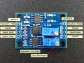
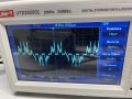
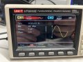
hi everyone. Im using ad620 amplifier module. The aim is to get an amplified sine wave. The problem arose right after the beginning: the sine wave on the output was way too destroyed. I thought the issue was with 7660 dc-dc converter, that didn’t provide the stable -5v, so I deleted it from the circuit and used another voltage source to make an external bipolar supply. Nothing changed. The picture of the oscilloscope is below.

I use waveform generator for sine wave generation.
connection: Vwg- S+
GND(wg) - gnd
V(+5V) - Vin
V(-5V) - V-
Oscilloscope - Vout
 

Attachments

Irving

Joined Jan 30, 2016
4,996
A schematic would be helpful...

never mind, found it:


What have you connected to S- ?

The AD620 is a differential opamp it expects a differential input. Try connecting S- to GND for a start...
 

crutschow

Joined Mar 14, 2008
38,316
And don't connect V- to an external power supply.
That voltage is provided internally by the 7660 converter.

Randomly connecting a circuit without knowing how it works seldom yields the desired results. :rolleyes:
 
Last edited:

Thread Starter

Ilua_S

Joined Apr 2, 2025
11
A schematic would be helpful...

never mind, found it:


What have you connected to S- ?

The AD620 is a differential opamp it expects a differential input. Try connecting S- to GND for a start...
I also tried to connect s- to gnd of the waveform generator but it wasn’t the issue. I found out that signal inputs should have a path to the ground via resistors. And it worked. Thank you for advice
 

sparky 1

Joined Nov 3, 2018
1,218
Welcome to AAC,
I am not familiar with the UTG932E function generator, what it's capability is for providing low enough range.
The function generator might not go less than 1Vpp. I simulated an attenuator for that to go lower in a range for that module.
Using a 10K the attenuator gives a value that can be seen on a multimeter. The advantage is switching the resistor.
Using a 100k resistor and higher a working AD620 module will greatly improve the resolution of the small signal.
A very low signal can be amplified in 2 stages such as 10 and then 100 and usually some error, but adjustable gain can help.

This circuit below is an attenuator. A high range and low range /10 or lower can be used to simulate a sensor.
This circuit has percent error needs some amplitude adjustment, divider compensation but it gets fairly close in the low range.
The module is given the name microvolt amplifier but using a 1 Ohm for R2 to produce a 10uV signal however the module
probably will have noise and other ailments in battery operation. The 100uV signal may give better expectations.

Setting the module.
When the sensor inputs are shorted the bottom potentiometer sets output to zero.
When a known attenuated source is applied, the top potentiometer is adjusted to the desired amplification factor.

The 10k resistor needs 26Ω but the 100k resistor needs 354Ω. A trusted meter (usually Vrms) shows attenuation factor of 10
When the switch is in position A the output is 1mV and when the switch is in position B the output is 100uV or 0.1 mV RMS
By applying attenuated signals the gain output of the module can be analyzed. The design started at 2.828 Vpp but the compensation
scheme needed 2.836 Vpp The function generator sine amplitude can be adjusted to 14.18 Vp which is 28.36Vpp maintaining the linearity.


AC signal attenuator.png
 
Last edited:

MisterBill2

Joined Jan 23, 2018
27,173
FIRST QUESTION is what is the gain setting of the instrument amplifier??
What it looks like to me is a package intended to work with a full resistance bridge sensor, either pressure or a load cell. In that case both S+ and S- will be voltages offset from the "ground" voltage, defined as zero. The total failure of that arrangement is that the common mode voltage is terribly wrong.
A schematic would be helpful...

never mind, found it:


What have you connected to S- ?

The AD620 is a differential opamp it expects a differential input. Try connecting S- to GND for a start...
NO!! The AD620 IS NOT a "differential op-amp!! It is a differential input INSTRUMENT AMP, That defines it as having an output based on the difference between the inputs, with the gain set by means of that resistance between the gain set terminals.
So before looking for an output it is useful to know what gain has been set. If the gain is set for 200 and the supplies are =5 and -5 volts, then any im=nput greater than 50 millivolts will be distorted.
 

Thread Starter

Ilua_S

Joined Apr 2, 2025
11
Welcome to AAC,
I am not familiar with the UTG932E function generator, what it's capability is for providing low enough range.
The function generator might not go less than 1Vpp. I simulated an attenuator for that to go lower in a range for that module.
Using a 10K the attenuator gives a value that can be seen on a multimeter. The advantage is switching the resistor.
Using a 100k resistor and higher a working AD620 module will greatly improve the resolution of the small signal.
A very low signal can be amplified in 2 stages such as 10 and then 100 and usually some error, but adjustable gain can help.

This circuit below is an attenuator. A high range and low range /10 or lower can be used to simulate a sensor.
This circuit has percent error needs some amplitude adjustment, divider compensation but it gets fairly close in the low range.
The module is given the name microvolt amplifier but using a 1 Ohm for R2 to produce a 10uV signal however the module
probably will have noise and other ailments in battery operation. The 100uV signal may give better expectations.

Setting the module.
When the sensor inputs are shorted the bottom potentiometer sets output to zero.
When a known attenuated source is applied, the top potentiometer is adjusted to the desired amplification factor.

The 10k resistor needs 26Ω but the 100k resistor needs 354Ω. A trusted meter (usually Vrms) shows attenuation factor of 10
When the switch is in position A the output is 1mV and when the switch is in position B the output is 100uV or 0.1 mV RMS
By applying attenuated signals the gain output of the module can be analyzed. The design started at 2.828 Vpp but the compensation
scheme needed 2.836 Vpp The function generator sine amplitude can be adjusted to 14.18 Vp which is 28.36Vpp maintaining the linearity.


View attachment 345990
Thank you for the clear explanation. I will try.
 

Thread Starter

Ilua_S

Joined Apr 2, 2025
11
FIRST QUESTION is what is the gain setting of the instrument amplifier??
What it looks like to me is a package intended to work with a full resistance bridge sensor, either pressure or a load cell. In that case both S+ and S- will be voltages offset from the "ground" voltage, defined as zero. The total failure of that arrangement is that the common mode voltage is terribly wrong.

NO!! The AD620 IS NOT a "differential op-amp!! It is a differential input INSTRUMENT AMP, That defines it as having an output based on the difference between the inputs, with the gain set by means of that resistance between the gain set terminals.
So before looking for an output it is useful to know what gain has been set. If the gain is set for 200 and the supplies are =5 and -5 volts, then any im=nput greater than 50 millivolts will be distorted.
regarding the gain settings I set it according to the oscilloscope avoiding the clipping for the 100mVpp signal. But the bridge thing didn’t come to my mind. I want to use this module to prototype an eeg device, so, I guess, there is no need for bridge circuits. My hypothesis is that I can wire s+ to the scalp and s- to the ear reference electrode and get the right signal on the output.
 

MisterBill2

Joined Jan 23, 2018
27,173
Oh Wow!! That is a very different application for an instrument amplifier. What will be an issue is the "common mode" voltage, because while the IA is amplifying the difference voltage between the two inputs, there is also the difference between those voltages and the "zero voltage reference " of the IA system. For an explanation of how to deal with the common mode voltage I suggest the ANALOG DEVICES website for information, because the typical Parts Seller will not have a clue as to what that is. And from amazon will be much less than that.

It may also be that others reading this thread know a lot about working with common mode voltages in an EEG type of application.
 
Last edited:
Top