Active Inductor

Thread Starter

Shruthi S

Joined Dec 6, 2021
7
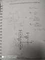
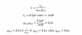
I don't know how to give values to bias currents here for the basic active inductor circuit, kindly help me to analyse the basic AI(Active Inductor Circuit). i have calculated gm1 and gm2 for both the transistor using inductance formula of Active Inductor, i don't know whether my method of calculation is correct or wrong.
 

Attachments

LvW

Joined Jun 13, 2013
1,752
I am not familiar with your two-transistor circuit. Thereforte, another hint:
A very exact and versatile active inductor (grounded) can be realized with two opamps (Antoniou`s GIC cicuit).
 

LvW

Joined Jun 13, 2013
1,752
From your first attachement I can derive that the shown circuit can simulate a lossy inductor only (parasitic resistances, parallel and in series )
 

LvW

Joined Jun 13, 2013
1,752
How do you intend to realize the two ideal current sources as shown in the circuit diagram?
Are you aware that any real realization will cause severe new losses?
I have many doubts that the whole approach would be a good one.
There are many oscillator circuits which are easier to realize and work much better.
 

Thread Starter

Shruthi S

Joined Dec 6, 2021
7
How do you intend to realize the two ideal current sources as shown in the circuit diagram?
Are you aware that any real realization will cause severe new losses?
I have many doubts that the whole approach would be a good one.
There are many oscillator circuits which are easier to realize and work much better.
I am new to analog circuits, I am designing circuits to analyse its behaviour , if the ideal current source is not the good choice then , what is the other solution that you can suggest to me. Do you want me to realise circuit with current mirrors ?
 

LvW

Joined Jun 13, 2013
1,752
I dont know what your final aim ist - just a working oscillator?
My recommendation: Use an opamp, four resistors and two capacitors.
 

Thread Starter

Shruthi S

Joined Dec 6, 2021
7
I dont know what your final aim ist - just a working oscillator?
My recommendation: Use an opamp, four resistors and two capacitors.
Ok, my aim is how the active inductor circuit actually work , what is the significance of the this circuit. I know theoretically but I wanted to analyse it practically by deigning an oscillator with active inductor
 

LvW

Joined Jun 13, 2013
1,752
In this case, I would concentrate - as a first step - to the inductor realization only.
Therefore, try to collect and simulate several methods for realizing active (and lossy) inductors .
 

Thread Starter

Shruthi S

Joined Dec 6, 2021
7
In this case, I would concentrate - as a first step - to the inductor realization only.
Therefore, try to collect and simulate several methods for realizing active (and lossy) inductors .
Ok Thankyou so much for your valuable time and suggestions. Next time I will come with some results of some Active inductor simulations
 

crutschow

Joined Mar 14, 2008
34,281
A simpler application for the active inductor would be in a filter circuit. such as a notch filter.

Below is the LTspice simulation of a gyrator inductor circuit using an op amp
For simulation purposes it is driven by an AC voltage source in series with a resistor.

The gyrator looks like an inductance to ground so it can't be used where a series inductor is needed..

1639159260314.png
 
Last edited:
Top