Active Baxandall Tone Control Not Responding on Bread Board

Thread Starter

aneves1

Joined Feb 7, 2025
33
Hello All,

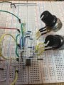
I've been trying to get a TMB tone stack to work for almost a year. I've recently settled to try and make a Baxandall tone control without avail. I've doubled checked my wiring and component values and everything looks fine (I will triple check values again). I've referenced this article: https://sound-au.com/dwopa2.htm analyzed it on LT Spice and the analysis looks fine. When I bread boarded this thing and tested it no response what so ever while adjusting the bass or treble pots. I'm getting a sine wave from the output (I guess that's a good start). Attached is my spice simulation. Any suggestions would be great!

Thank You,
Aneves
 

Attachments

Last edited by a moderator:

MrChips

Joined Oct 2, 2009
34,628
The spice simulation works hence we don’t need to see that. We do need to see your circuit diagram and photos of your actual breadboard construction. Rather than test the complete circuit, you can test sections at a time. Do you have access to an oscilloscope?
 

schmitt trigger

Joined Jul 12, 2010
2,027
This is one of those projects in which, at a bare minimum, requires a variable frequency sinewave generator and a scope, to properly troubleshoot it.
If you don’t own them, can you at the very least borrow them?
EDIT: a stable, DC supply is another plus, but one can always use batteries in a pinch.
 

Thread Starter

aneves1

Joined Feb 7, 2025
33
The spice simulation works hence we don’t need to see that. We do need to see your circuit diagram and photos of your actual breadboard construction. Rather than test the complete circuit, you can test sections at a time. Do you have access to an oscilloscope?
The circuit diagram is as in the spice schematic. Attached is a pic of the circuit; and yes I have a complete test bench (ie: scope, signal generator and bench multimeter). I will clean up the wiring on the bread board if so needed.
 

Attachments

Thread Starter

aneves1

Joined Feb 7, 2025
33
This is one of those projects in which, at a bare minimum, requires a variable frequency sinewave generator and a scope, to properly troubleshoot it.
If you don’t own them, can you at the very least borrow them?
EDIT: a stable, DC supply is another plus, but one can always use batteries in a pinch.
I have a complete test bench.
 

MrChips

Joined Oct 2, 2009
34,628
The circuit diagram is as in the spice schematic. Attached is a pic of the circuit; and yes I have a complete test bench (ie: scope, signal generator and bench multimeter). I will clean up the wiring on the bread board if so needed.
Sorry, I don’t open spice files. Can you post the circuit schematics?
What are you using to power the op amp?
 

Alec_t

Joined Sep 17, 2013
15,101
no response what so ever
If there is no voltage change anywhere in the circuit then the tone controls are likely not connected correctly on the breadboard.
Tell us which op-amp you are using and what the DC voltages are on all the op-amp pins.
 

Thread Starter

aneves1

Joined Feb 7, 2025
33
If there is no voltage change anywhere in the circuit then the tone controls are likely not connected correctly on the breadboard.
Tell us which op-amp you are using and what the DC voltages are on all the op-amp pins.
The op-amp is an LM358. The power source is a 0 ~ 9.5 volt power adapter (Since, this circuit will be used in a guitar pedal). Since, the schematic doesn't show how the offset voltage is set. This is done with a virtual ground circuit and with a voltage divider used to lift the positive input of the op-amp ~ 4.2 volts.
 

crutschow

Joined Mar 14, 2008
38,316
Okay, the sim may work with an ideal op amp, but not with a model of the LM358.
You have a 4.5V offset on the amp's (+) input so the output saturates when you DC ground the input from your AC source.
So be aware that doing a sim with ideal components can lead to results drastically different than a real circuit.

Need to add a DC block capacitor at the input (C3 below):

Of course, the output will then also have a 4.5Vdc offset, so you need a capacitor there for a 0Vdc centered AC signal.

1760730334888.png
 
Last edited:

Thread Starter

aneves1

Joined Feb 7, 2025
33
I already added blocking caps to the input and output of the bread boarded circuit. I didn’t update the schematic with blocking caps. Thanks for the advice on using actual industry configured components. I still have same issue.
 

Thread Starter

aneves1

Joined Feb 7, 2025
33
If there is no voltage change anywhere in the circuit then the tone controls are likely not connected correctly on the breadboard.
Tell us which op-amp you are using and what the DC voltages are on all the op-amp pins.
The op-amp is an LM358. I don’t understand the second part of your question. Pin4 is the ground pin Pin 5 is 9.5 volts. Forgive my ignorance are you saying that all of the pins have DC voltages? What exactly should I be checking?
 

Thread Starter

aneves1

Joined Feb 7, 2025
33
This is one of those projects in which, at a bare minimum, requires a variable frequency sinewave generator and a scope, to properly troubleshoot it.
If you don’t own them, can you at the very least borrow them?
EDIT: a stable, DC supply is another plus, but one can always use batteries in a pinch.
I have a full workbench.
 

Thread Starter

aneves1

Joined Feb 7, 2025
33
The spice simulation works hence we don’t need to see that. We do need to see your circuit diagram and photos of your actual breadboard construction. Rather than test the complete circuit, you can test sections at a time. Do you have access to an oscilloscope?
Yes
 

Thread Starter

aneves1

Joined Feb 7, 2025
33
I’m injecting a 200Hz, 500 mVpp sine wave into the input of the circuit. I’ve checked all of the nodes and I’m seeing that 200Hz sine wave at all the nodes. As well as at the output of the op-amp. Based on that I’m assuming all the connections are secure.

Issue: When I change the bass potentiometer (since 200hz is a bass frequency). I should see signal amplification or attenuation based on wether I’m turning the potentiometer up or down at the output. I’m not seeing any amplitude change at all. That’s what I mean by not responding.
 
Top