Facebook
 Google
 GitHub
 Linkedin
Hi,
Im completely green, have only been watching around 100 videos and are now starting to experiment myself.
Im starting out with making a startling scarecrow to scare away the deers from my rose garden.
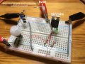
So I thought I would make it with a PIR which sends voltage to a transistor which activates a mosfet for a larger current to run a motor or a solenoid of some kind.
The following circuits PIR does work (blue LED lights). It lights up the LED for 3 sekunds and turns off.
The circuits MOSFET also works fine (green LED lights) if I activate it manually with the wire floating in the air.
My question is, and I have tried several places, where do I connect the wire to activate the mosfet, and do I have a circuit that actually can do that?
The first photo should give you some information about the circuit.
It is suppose to run on 6-12 volts, I will adjust it when I figure out what its going to run.
from
Christian Nielsen, Denmark
Im completely green, have only been watching around 100 videos and are now starting to experiment myself.
Im starting out with making a startling scarecrow to scare away the deers from my rose garden.
So I thought I would make it with a PIR which sends voltage to a transistor which activates a mosfet for a larger current to run a motor or a solenoid of some kind.
The following circuits PIR does work (blue LED lights). It lights up the LED for 3 sekunds and turns off.
The circuits MOSFET also works fine (green LED lights) if I activate it manually with the wire floating in the air.
My question is, and I have tried several places, where do I connect the wire to activate the mosfet, and do I have a circuit that actually can do that?
The first photo should give you some information about the circuit.
It is suppose to run on 6-12 volts, I will adjust it when I figure out what its going to run.
from
Christian Nielsen, Denmark
Attachments
-
 213.8 KB Views: 72
 -
 210.5 KB Views: 61
 -
 196.7 KB Views: 59
 -
 181 KB Views: 57