 Facebook
 Google
 GitHub
 Linkedin
I put together a wheatstone bridge to measure conductivity/resistance of semisolids and gels. I found that trying to measure conductance directly with DC led to weird inconsistent effects due to ion migration (I think), and so I started using AC, and I was getting pretty good numbers.
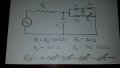
My understanding of the mechanics of the wheatstone bridge for these kinds of measurements is that it is essentially a "balancing" act for the current running through the galvanometer. Tweaking the rheostat too far in either direction allows current to flow through because of Kirchoff's and Ohm's Laws. The schematic of my device is posted below.
Here's the weird part: My bridge is unidirectional. I start with the potentiometer (used as a rheostat) at zero. I see a current register on the galvanometer. I can zero it out carefully by increasing the resistance of the potentiometer, but if I blow a little past the point at which the resistances are equal... nothing happens. Galvanometer continues to read zero. So current doesn't return as the potentiometer resistance gets arbitrarily large, unless I dial it back to the point before it went to zero. I've tested several known resistances, finding the zero point in one direction, and the device gives me an accurate resistance reading. I just have absolutely no clue why it's asymmetrical this way.
Explanation of the Schematic and Circuit:
I used an 100V EL-Wire inverter as my AC source rather than run a current limited line voltage or use a bench power supply because it's very important that the circuit be portable. But, EL-wire inverters are very unstable in low or no load conditions and will fail with just pure resistance. I learned this by making magic smoke. I looked up other methods of pure or semi-pure sine wave inversion from DC, and since most that I found were basically variants of 555 timer astable multivibrators, I decided to keep using EL-wire inverters, since that's pretty much what they are, but I decided to also put a simulated load on there since a capacitative and resistive load is necessary to keep the frequency and peak voltage within the tolerance of the device. At first I tried EL-wire itself, but it seemed to severely limit my current and the galvanometer always read zero. I then used a 0.022μF capacitor and a 1500Ω resistor to limit current and keep the magic smoke inside the inverter and to stabilize the output, and that seems to work fine as a sort of "ballast" stabilizing the inverter, but I wonder if it could be causing the phenomenon... it shouldn't. The capacitor causes current to lead voltage but this should make no difference to the application, since the current is still there.
Thanks in advance for the help.
Attachments
-
 275.7 KB Views: 12


