Facebook
 Google
 GitHub
 Linkedin
This is related to my thread a couple weeks ago about problems with a variable reluctance sensor. Finally got the speedometer to work by disconnecting the cruise control (though haven't yet figured out why that works).
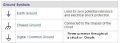
It did highlight my confusion about ac in a car. In a house, I mostly understand hots, neutrals and grounds. In a car, there is no 'neutral', and everything I've read about var. rel. sensors calls one wire the signal and one the ground. Some schematics show one wire as "hi' and one as 'low'. What??
I'm hopeful getting a better understanding of how this works may help me figure out where my problem now lies.
Thanks!


")