
Hi,
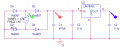
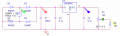
I am trying to model a simple 230V/50Hz to 5VDC power supply to drive a downstream circuit. I am using a transformer to get 12VAC (modelled as V1); this feeds a bridge rectifier (D2-D5), then filter (C1) before being passed into a voltage regulator (U2, C2, C3).
I get a perfect output as can be seen below (blue trace showing a stable 5V).

However, when I place a load on the generated DC (in this case, it is a high resistance potentiometer (R1), the results become very messy. I don't understand why this is happening and would appreciate any advice out there.


I am trying to model a simple 230V/50Hz to 5VDC power supply to drive a downstream circuit. I am using a transformer to get 12VAC (modelled as V1); this feeds a bridge rectifier (D2-D5), then filter (C1) before being passed into a voltage regulator (U2, C2, C3).
I get a perfect output as can be seen below (blue trace showing a stable 5V).
However, when I place a load on the generated DC (in this case, it is a high resistance potentiometer (R1), the results become very messy. I don't understand why this is happening and would appreciate any advice out there.
Attachments
-
 18.6 KB Views: 2
 -
 18.8 KB Views: 3
 -
 23.3 KB Views: 3
 -
 200.8 KB Views: 2
 -
 26.3 KB Views: 2


