AC supply to LED's - how do I eliminate flicker?

MrAl

Joined Jun 17, 2014
13,724
Hi,

I think what i would try doing is to try to break up the two strings so you can power them individually.
If you can break even one end of the two strings then you can power them individually. That means you can use full wave rectification and that means the pulse rate will be 100 times per second for both strings.

The problem is, if 50Hz bothers you then you have to go to a higher frequency one way or another if you cant break up the two strings somehow. That requires converting AC to DC then chopping it back up into maybe 500Hz or something.

Another idea, a little more complicated, is something like the following...
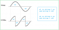
The mains frequency is 50Hz and that's got a period of 20ms, so one half cycle which is 180 degrees has a 10ms period. If you incorporate an H bridge transistor bridge, you can chop up that into 90 degree portions, where the first 90 degree portion goes unchanged and the second 90 degree portion gets inverted.
The base line frequency is 50Hz so that means that without modification the first string turns on for 10ms then the second string for the next 10ms, and that repeats 50 times per second. By chopping up the line voltage the first string would be 'on' for 5ms and the second for the next 5ms, and that would repeat 100 times per second. The waveshape will be less than ideal, but it may be enough to lower the blinking effect to an acceptable level. If not, you have to go to AC to DC then chop up to whatever frequency you want.

Here is a drawing of the waveshapes that would be driving the two strings. The 100Hz wave is the chopped version and may help with the blinking problem although there is a chance that it will not help enough because the average intensity is the same over a full period. It should help some though because of the integrating effect the human eyes have for changing light levels.
Chopper-01.png
 

MrSalts

Joined Apr 2, 2020
2,767
The two strings of LEDs essentially become the rectifier in many cheap lights. With the second string close to the first, the flash is essentially eliminated as one set is on with a very short off time in between.
 

MisterBill2

Joined Jan 23, 2018
27,726
The flicker is seen because for a big portion of the cycle the voltage is not high enough to illuminate the LEDs. So it is the dark time creating the flicker. And that is because the transformer is feeding a sine wave, while that controller probably fed switched DC. So an "H-Bridge" switching circuit will solve the problem, and you can drive it with the 50 HZ and not need an oscillator for a higher frequency, SO a switching driver will work, but you will probably want a lower DC supply voltage to hold the power to a reasonable level, because the square wave will provide a longer period of current flow each cycle.
 

drjohsmith

Joined Dec 13, 2021
1,620
The flicker is seen because for a big portion of the cycle the voltage is not high enough to illuminate the LEDs. So it is the dark time creating the flicker. And that is because the transformer is feeding a sine wave, while that controller probably fed switched DC. So an "H-Bridge" switching circuit will solve the problem, and you can drive it with the 50 HZ and not need an oscillator for a higher frequency, SO a switching driver will work, but you will probably want a lower DC supply voltage to hold the power to a reasonable level, because the square wave will provide a longer period of current flow each cycle.
For conversation,
if a led flashes for 10 us every 20ms or for 100us every 20ms
provided the brightness is similar, would it look the same to a human ?
 

BobTPH

Joined Jun 5, 2013
11,570
In the second case, it would look much brighter. That is the basis of PWM dimming of LEDs.

Don’t know whether there is any difference in appearance of flicker.
 
Last edited:

drjohsmith

Joined Dec 13, 2021
1,620
In the second case, it would look much brighter. That is the basis of PWM dimming of LEDs.

Don’t know whether there is any difference in appearance of flicker.
Sorry, I tried to cover brightness by saying same , but my English not good there,
I think, if the current was adjusted so the apparent brightness was the same in both cases, the flicker or lack of it would be the same,

but am open to thoughts,
 

MisterBill2

Joined Jan 23, 2018
27,726
Once again the flicker appears because the LEDs do not illuminate for a significant portion of the sine wave. I don't have a simple scheme for producing square waves from rectified sine waves.
But consider an H-Bridge with suitable mosfets and using a digital driver to produce the square wave, with the supply voltage being adjusted for the correct power level?
 

drjohsmith

Joined Dec 13, 2021
1,620
@MisterBill2
You say "Once again the flicker appears because the LEDs do not illuminate for a significant portion of the sine wave. "

This is what I'm wondering about.,
in the circuit the OP has, the Leds "flash" every 20 ms, assuming European mains,
If the flash was on for 10 us or 1 ms, and adjusted to the same apparent brightness to the user,
does the portion of the 20 ms matter to the amount of flicker the user sees in a static display ?

Im thinking probably about persistence effect
https://en.wikipedia.org/wiki/Persistence_of_vision
 

DC_Kid

Joined Feb 25, 2008
1,242
Once again the flicker appears because the LEDs do not illuminate for a significant portion of the sine wave. I don't have a simple scheme for producing square waves from rectified sine waves.
But consider an H-Bridge with suitable mosfets and using a digital driver to produce the square wave, with the supply voltage being adjusted for the correct power level?
A zener will clip sine wave. 1k inline with a 12v zener, apply 24vac, as the sine rises to 12v the point between 1k and zener looks like sine, but above 12v the voltage looks like flat 12v, like square wave.
 

BobTPH

Joined Jun 5, 2013
11,570
@MisterBill2
You say "Once again the flicker appears because the LEDs do not illuminate for a significant portion of the sine wave. "

This is what I'm wondering about.,
in the circuit the OP has, the Leds "flash" every 20 ms, assuming European mains,
If the flash was on for 10 us or 1 ms, and adjusted to the same apparent brightness to the user,
does the portion of the 20 ms matter to the amount of flicker the user sees in a static display ?

Im thinking probably about persistence effect
https://en.wikipedia.org/wiki/Persistence_of_vision
I think an experiment is in order. My guess is that it does not change the flicker as long as the apparent brightness is the same.
 

MisterBill2

Joined Jan 23, 2018
27,726
With a sine wave the LEDs are off at least half of the time, AND 100% of the opposite half cycle. With a square wave they will have a 50% DUTY CYCLE, OR CLOSE TO IT. So an H-bridge driver with mosfets adequately driven into saturation so that the duty cycle will be high enough.
 

drjohsmith

Joined Dec 13, 2021
1,620
With a sine wave the LEDs are off at least half of the time, AND 100% of the opposite half cycle. With a square wave they will have a 50% DUTY CYCLE, OR CLOSE TO IT. So an H-bridge driver with mosfets adequately driven into saturation so that the duty cycle will be high enough.
Assuming same perceived brightness, does the amount of time a leds on in a cycle affect the perceived flash or is it only the period between turn on ?
 

MrAl

Joined Jun 17, 2014
13,724
Hi,

A flash is just a period of 'on' followed by a period of 'off'.
The 'on' portion will be integrated by the eye to a certain amount. That means that the intensity over time is summed for the period of the 'on' time. During the initial 'off' time, that integration will keep the eye thinking there is still some brightness until the perceived brightness integrates to zero, which happens due to the length of the 'off' time. If the 'off' time is long enough, the eye will perceive a decrease in brightness. If the 'off' time is short, it will not. If it is somewhere in between long and short the eye may detect a decrease in brightness which would be perceived as a slight blink not a complete blink.

Because of the integration effect the shape of the intensity curve during the 'on' time and also the length of the 'on' time will produce some perceived average brightness which will then be comparative to the darkness when 'off'. So it depends on both the 'on' time vs 'off' time AND the wave shape during the 'on' time assuming the 'off' time is completely off. If the 'off' time is not completely off, then that shape will also play a part the perception of a blink vs no blink vs a slight blink.

I can see a 60Hz half wave rectified sine blink but i cant detect a 60Hz full wave rectified sine (really 120Hz) blink unless i move my head fast or sweep the LED across my field of vision.
 

crutschow

Joined Mar 14, 2008
38,573
I also think the perceived flicker is mainly determined by the blink rate, and is largely unaffected by the duty-cycle, which only affects perceived brightness if the blink rate is high enough to not be noticeable.
 

ElectricSpidey

Joined Dec 2, 2017
3,340
Over the years I have noticed more flicker at the low end of the PWM scale such as say 10% as opposed to the higher percentages and this is only at the lower frequencies.

But BUT...this could only be me I can see flicker all the way up to nearly 1000Hz.

I usually use 3kHz in my projects.
 

MrAl

Joined Jun 17, 2014
13,724
I also think the perceived flicker is mainly determined by the blink rate, and is largely unaffected by the duty-cycle, which only affects perceived brightness if the blink rate is high enough to not be noticeable.
Hi there,

I wanted to say both blink rate and duty cycle in order to cover all extremes.
For example, 1 percent duty cycle may look barely lit while 99 percent duty cycle would probably look always on unless the blink rate was so low that the 'off' time was extreme too like 5 seconds or even less really.

So let's see that gives us several extremes...
1 percent and 10kHz vs 1 percent and 1Hz.
99 percent and 10kHz vs 99 percent and 0.01Hz.
1 percent and 10kHz vs 99 percent and 10kHz,
1 percent and 0.01Hz and 99 percent and 0.01Hz.

Considering all extremes i think we see differences for different cases of both.
In my experience i an see a blink with a 50 percent duty cycle sine wave but not with a full wave sine, with the base frequency 60Hz.

To find out using a little math, or electronics, we should be able to filter a pulse of varying duty cycle and frequency with an RC low pass filter and that RC acts like an integrator too. The output will show what we might see, and we can set the RC time constant to be something like the human eye response.
I guess we can also try this using an arbitrary waveform generator or a microcontroller programmed to do all extremes in succession and actually look at the response with our actual eyes. Any up to the task?
 

drjohsmith

Joined Dec 13, 2021
1,620
Hi there,

I wanted to say both blink rate and duty cycle in order to cover all extremes.
For example, 1 percent duty cycle may look barely lit while 99 percent duty cycle would probably look always on unless the blink rate was so low that the 'off' time was extreme too like 5 seconds or even less really.

So let's see that gives us several extremes...
1 percent and 10kHz vs 1 percent and 1Hz.
99 percent and 10kHz vs 99 percent and 0.01Hz.
1 percent and 10kHz vs 99 percent and 10kHz,
1 percent and 0.01Hz and 99 percent and 0.01Hz.

Considering all extremes i think we see differences for different cases of both.
In my experience i an see a blink with a 50 percent duty cycle sine wave but not with a full wave sine, with the base frequency 60Hz.

To find out using a little math, or electronics, we should be able to filter a pulse of varying duty cycle and frequency with an RC low pass filter and that RC acts like an integrator too. The output will show what we might see, and we can set the RC time constant to be something like the human eye response.
I guess we can also try this using an arbitrary waveform generator or a microcontroller programmed to do all extremes in succession and actually look at the response with our actual eyes. Any up to the task?
To clarify

you say " 1 percent duty cycle may look barely lit "
where as I was saying with the same apparent brightness,
which as the current is "with out limit" in the OPs spec, would I'd say be more like their system,
 

Thread Starter

Shepton

Joined Feb 7, 2023
2
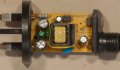
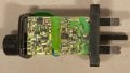
Thank you everyone for your comments. I hadn't considered that a square wave would give a different perceived effect than a sine wave which would illuminate the LED for a shorter period at the same frequency. However these lights had a number of programmes one of which could make the whole string slowly get brighter and then slowly dim, presumably it worked by cutting up the wave to provide a shorter duration at 'on' while the frequency would remain the same so that would counter this idea - the LEDs would when dim be on for a shorter duration. For what its worth I have included images of the original circuit - frustrating that I have no oscilloscope so have no idea what frequency it works at. I think I will try and build a circuit using an H bridge as has been suggested and experiment with the 50hz supply to switch it and see if it gives a perceived steady light. Again - thanks for all your input.LED PSU-2.jpgLED PSU.jpg
 

MrAl

Joined Jun 17, 2014
13,724
Thank you everyone for your comments. I hadn't considered that a square wave would give a different perceived effect than a sine wave which would illuminate the LED for a shorter period at the same frequency. However these lights had a number of programmes one of which could make the whole string slowly get brighter and then slowly dim, presumably it worked by cutting up the wave to provide a shorter duration at 'on' while the frequency would remain the same so that would counter this idea - the LEDs would when dim be on for a shorter duration. For what its worth I have included images of the original circuit - frustrating that I have no oscilloscope so have no idea what frequency it works at. I think I will try and build a circuit using an H bridge as has been suggested and experiment with the 50hz supply to switch it and see if it gives a perceived steady light. Again - thanks for all your input.View attachment 287606View attachment 287607
Ditch that hero and get yourself a zero :)

If you go custom converter with rectifier, filter, H bridge, you can use higher frequencies like 1kHz. Zero blink perception.
 

MisterBill2

Joined Jan 23, 2018
27,726
There is a fair amount of published design work concerning H-Bridges and PWM, including schemes using a separate dvice for the duty cycle control to avoid shoot-through issues with the bridge portion of the circuit. But not on yootoob or the other cartoon sites. semiconductor manufacturer websites are a good place to start
 
Top