AC Line neutral sensing with resistor divider for mcu ADC

Thread Starter

ilginsarican

Joined Jul 13, 2017
147
Hello,
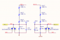
I am trying to measure AC line and neutral voltage (50Hz) with resistor divider.
The schematic and oscilloscope measurement are attached.
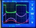
The green signal is neutral and purple is line. The red signal is the result of math fuction of scope which is line minus neutral signal.
I dont understand why is the neutral (green) has offset near zero voltage?
So the red signal is not exactly a sine.
 

Attachments

ericgibbs

Joined Jan 29, 2010
21,395
Hi ilgin,
This LTSpice idealist simulation shows that the VAC_L and VAC_N never reach the voltages as shown in your scope image.
I have assumed a 230Vrms mains supply at 50Hz.

Is your posted circuit correct?

Also on AC mains supplies the N line can have a voltage relative to the Earth, which could give you a 0V offset.
E
EG57_ 2186.png
 

ronsimpson

Joined Oct 7, 2019
4,649
If the ADC spans 0 to 3.3V I would do it this way. Note the new resistor. RAC7 and Rnew in parallel have the 7.5k value. But now you get 1/2 of the DAC range when AC L is at 0V. Now you can read a positive or a negative voltage.
Now 1000 0000 or 0111 111 is 0V. Use signed number.
1729084707410.png
 

Thread Starter

ilginsarican

Joined Jul 13, 2017
147
Hi ilgin,
This LTSpice idealist simulation shows that the VAC_L and VAC_N never reach the voltages as shown in your scope image.
I have assumed a 230Vrms mains supply at 50Hz.

Is your posted circuit correct?

Also on AC mains supplies the N line can have a voltage relative to the Earth, which could give you a 0V offset.
E
View attachment 333768
Actually the circuit is an Inverter design. I am trying to measure AC output line and neutral voltage with microcontroller. The output voltage was 115VAC RMS when I took scope measurements.
 

ericgibbs

Joined Jan 29, 2010
21,395
Hi ilgin,
Using your latest circuit and a Vsupply of 115Vrms, this is what an LTS simulation shows for the VL and VN values.

EEG57_ 2190.png
 

Thread Starter

ilginsarican

Joined Jul 13, 2017
147
If the ADC spans 0 to 3.3V I would do it this way. Note the new resistor. RAC7 and Rnew in parallel have the 7.5k value. But now you get 1/2 of the DAC range when AC L is at 0V. Now you can read a positive or a negative voltage.
Now 1000 0000 or 0111 111 is 0V. Use signed number.
View attachment 333770
Hi, I solved the problem. The problem was caused by the PCB layout. I moved R4 and C1 closer to the MCU and the problem was solved. Thanks for your help.
 

MisterBill2

Joined Jan 23, 2018
27,187
Consider that this is a switching inverter with neither the line nor the neutral being related to each other. So to measure the actual output voltage an actual transformer will be the way to measure it accurately.
 
Top