A quiz that I give all my electronics students at mid-term

Thread Starter

KL7AJ72

Joined Apr 15, 2021
22
120V mains is relatively benign compared to the voltage in the resonant circuit!
But it's NOT resonant....that's the whole point. There are two possible solutions, one on the high side of resonance, and one on the low side. The important factor is the net reactance...and for this problem, the sign of the net reactance doesn't matter.
 

Ian0

Joined Aug 7, 2020
13,228
But it's NOT resonant....that's the whole point. There are two possible solutions, one on the high side of resonance, and one on the low side. The important factor is the net reactance...and for this problem, the sign of the net reactance doesn't matter.
"Resonance describes the phenomenon of increased amplitude that occurs when the frequency of an applied periodic force (or a Fourier component of it) is equal or close to a natural frequency of the system on which it acts." Wikipedia
 

Thread Starter

KL7AJ72

Joined Apr 15, 2021
22
View attachment 301458
You have a 12volt 25 watt lamp that you need to run off of house current (120VAC, 60 Hz in the U.S.). You can drop the voltage to the proper voltage efficiently using just series reactance. With the circuit above, what value of L1 do you need to make the lamp happy? (Capacitor C1 is non-negotiable.)
What I like about this sort of problem is that there are several very different approaches to figuring it out. It's a great exercise in sanity checks. One way I like is to FIRST figure out the power factor. (P.S., I used ICAP4 to draw this, which doesn't have a lamp model, so I had to roll my own. :) ) We know that the total circuit current is the same as the lamp current, which is 25/12 or 2.08 amps. So the circuit apparent power is 120x2.08 or 249.6 W (we can round up to 250W. The True power is 25 watts, because the lamp is the only thing that dissipates power. So the power factor is 25/250 or 0.1.

Now, once we know the power factor, we can figure out the phase angle., the arccosine of .1. or 84.26 degrees.

continued....
 

Thread Starter

KL7AJ72

Joined Apr 15, 2021
22
What I like about this sort of problem is that there are several very different approaches to figuring it out. It's a great exercise in sanity checks. One way I like is to FIRST figure out the power factor. (P.S., I used ICAP4 to draw this, which doesn't have a lamp model, so I had to roll my own. :) ) We know that the total circuit current is the same as the lamp current, which is 25/12 or 2.08 amps. So the circuit apparent power is 120x2.08 or 249.6 W (we can round up to 250W. The True power is 25 watts, because the lamp is the only thing that dissipates power. So the power factor is 25/250 or 0.1.
Now, once we know the power factor, we can figure out the phase angle., the arccosine of .1. or 84.26 degrees.

continued....
Now the next morsel of information we need is the circuit RESISTANCE, which is simply the lamp resistance, which is 25V/2.08 or 5.77 ohms. Oh yes, we also know the total circuit Z, which is 120/208 which is 57.7 ohms. Now all we need to do is calculate the required reactance. Z^2 = R^2 + X^2. Now solve for X
 

Ian0

Joined Aug 7, 2020
13,228
If the phase angle is 84° then the real part of the impedance is negligible and an assumption that the circuit is entirely reactive will give less error than the component tolerances. (I've been in the real world too long to believe in absolute component values)
 

Thread Starter

KL7AJ72

Joined Apr 15, 2021
22
If the phase angle is 84° then the real part of the impedance is negligible and an assumption that the circuit is entirely reactive will give less error than the component tolerances. (I've been in the real world too long to believe in absolute component values)
It is certainly MOSTLY reactive, but this circuit actually works.
In my electronics classes, someone invariably asks, "What should we use for pi...3.14159 or 3.1416?" I always tell them, "How about 3.1?" I then explain that since resistor color codes only have two significant digits, it's pointless to use more than two significant digits for PI in any calculation. Of course, for instrumentation we want higher precision, but just about ANY radio circuit will basically function with 20% tolerances. :)
 

Pyrex

Joined Feb 16, 2022
526
In practice such a circuit will show a poor performance.
When we were students, we made a night light in the living room, an incandescent lamp (3.5V 0.25A) was connected in series with a capacitor and powered from the mains . It was lit dimly , 24/7. Lifespan was about one week only. Guess why this happened?:)
 

Thread Starter

KL7AJ72

Joined Apr 15, 2021
22
In practice such a circuit will show a poor performance.
When we were students, we made a night light in the living room, an incandescent lamp (3.5V 0.25A) was connected in series with a capacitor and powered from the mains . It was lit dimly , 24/7. Lifespan was about one week only. Guess why this happened?:)
You used and electrolytic capacitor. I would recommend an oil motor-start capacitor. :)
 

Thread Starter

KL7AJ72

Joined Apr 15, 2021
22
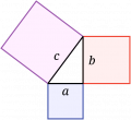
You say me an impossible thing.... Its actually the 5th or 6th grade thing in geometry.
Here in our case the capacitive current is (b) upward, the (b) downward is inductive current, the (a) is active current and (c) is complex current absolute value.
View attachment 301557https://en.wikipedia.org/wiki/Pythagoras
Are you in the U.S.? Here at least, by convention Inductive reactance is up, capacitive down. But again, that might just be US. :)
 

Pyrex

Joined Feb 16, 2022
526
You used and electrolytic capacitor. I would recommend an oil motor-start capacitor. :)
Oh, man , no, no. I did knew what for is an electrolytic capacitor... It was a paper-in-oil capacitor, rated to 250VAC.
Lamp's lifespan was a week or so. A week only:)
 
Top