A little messup with the transmitter. Bought the wrong IC.

Thread Starter

kris_maher

Joined Apr 24, 2009
90
Hi,

I was meant to purchase the 4069 CMOS Hex inverter for my transmitter circuit (amplifies 5V p-p to 20V p-p to go into the ultrasonic transducer) however I mistakenly picked up the 4009 Hex Buffer instead.

As I suspected it didn't amplify at all, I'm just wondering if my suspicion is correct. Thanks, I need to know.

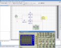
EDIT: I quickly simulated in multisim with a buffer instead of the 4069 hex inverters and it does indicate error.
 

Attachments

Last edited:

bertus

Joined Apr 5, 2008
22,972
Hello,

When using a buffer the outputs will go up and down at the same time.
There will be no change in amplitude on the load.
When you change U4D in your schematic to an inverter it will work, even with the others as buffers.

Greetings,
Bertus
 

millwood

Joined Dec 31, 1969
0
logically the two ics are identical: they take an input and invert it - input 1 -> output 0, and input 0 -> output 1.

there are some slight differences between the two but if a 4009 should work where a 4069 works but the reverse may not be true.
 

jpanhalt

Joined Jan 18, 2008
11,087
This may be naive, but it looks to me that the plan was to take the signal, invert it, and add that back to the uninverted signal to get twice the amplitude.

I can't run a simulation to know if that will work; however, I can say that one basic difference between a non-inverting buffer and an inverter is that two inversions give a positive. There is no way to get an inversion (negative) with only a non-inverting buffer.

So, if you want to test your plan, I think you need an inverter.

John
 

Thread Starter

kris_maher

Joined Apr 24, 2009
90
ahh ok. Because it doesn't seem to work using the 4009. There seems to be no amplification at all. I've just done the top half so far to check. I'll double check things.
I'll need to grab myself the 4069 tomorrow.

@ Bertus,
So your implying that it won't work on the buffer?
 

millwood

Joined Dec 31, 1969
0
This may be naive, but it looks to me that the plan was to take the signal, invert it, and add that back to the uninverted signal to get twice the amplitude.

I can't run a simulation to know if that will work; however, I can say that one basic difference between a non-inverting buffer and an inverter is that two inversions give a positive. There is no way to get an inversion (negative) with only a non-inverting buffer.

So, if you want to test your plan, I think you need an inverter.

John
both are inverters. the "buffer" designation only means it has higher current output capability - so 4009 is a beefier version of 4069, from the point of view of output capability.

whether your schematic works or not depends on many factors; whether your simulation works depends on many more factors. the fact that your simulation doesn't work doesn't mean the 4009 cannot be used in place of a 4069. or vice versa.

it all depends on what you want to do and if you can get it done right.
 

millwood

Joined Dec 31, 1969
0
ahh ok. Because it doesn't seem to work using the 4009. There seems to be no amplification at all. I've just done the top half so far to check. I'll double check things.
I'll need to grab myself the 4069 tomorrow.

@ Bertus,
So your implying that it won't work on the buffer?
nor would there be any amplification had you used 4069: those are digital devices.

that's not to say that you cannot use those devices for analog purposes, :). and yes, they can amplify analog signals.
 

Thread Starter

kris_maher

Joined Apr 24, 2009
90
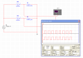
the simulation is using 4069, it works.

I'm using 4009 right now, it doesn't work. It is 5V p-p square wave from the micro, so on the micro-controller pin it shows 2.5V on the multimeter. Anyways on the output of the top half of the above circuit it still shows 2.5V. So basically it did nothing. All the connections on the actual thing match on what the simulation uses.
 

millwood

Joined Dec 31, 1969
0
the simulation is using 4069, it works.

I'm using 4009 right now, it doesn't work. It is 5V p-p square wave from the micro, so on the micro-controller pin it shows 2.5V on the multimeter. Anyways on the output of the top half of the above circuit it still shows 2.5V. So basically it did nothing. All the connections on the actual thing match on what the simulation uses.
the 4009 is doing exactly what it is supposed to do. and I would be surprised if a 4009 would have done anything else.

what else do you expect?
 

jpanhalt

Joined Jan 18, 2008
11,087
both are inverters. the "buffer" designation only means it has higher current output capability - so 4009 is a beefier version of 4069, from the point of view of output capability.
Sorry about that. I didn't check the datasheet and went just from the original description.

I don't believe the circuit , as drawn, will work for a more fundamental reason, assuming all the gates have the same 10-V supply and ground reference. I think if the OP draws it out on paper, he will see why it doesn't multiply the voltage.

John
 

millwood

Joined Dec 31, 1969
0
here is a quick check to show you that those two chips are identical, logically.

so I am not sure what you are expecting your 4069 to do and how a 4009 would have failed to do it.

if anything, you can get a situation where a 4009 will work but a 4069 will not.
 

Attachments

bertus

Joined Apr 5, 2008
22,972
Hello,

I have looked up the 4009, it is a lower power version of the 4069.
The schematic you use is probably to amplify the signal for a ultrasonic transducer.
Both should work, though I do not know if the 4009 is powerfull enough.

Greetings,
Bertus
 

Thread Starter

kris_maher

Joined Apr 24, 2009
90
Ok this is what eblc1388 came up with a few months back when I dug through my previous post.


He used hex schmitt triggers. The right side is basically similar to what I have.

Oh btw the VDD on the 4009 is powered up to 5V (max 22V supply). The VSS and VCC are not connected to anything. Not sure if this matters or not. I might have sounded stupid just now.
 
Last edited:

millwood

Joined Dec 31, 1969
0
Hello,

I have looked up the 4009, it is a lower power version of the 4069.
the biggest difference is in their current capability: the name "buffer" gives that away.

4009 is essentially a 4069 where the output goes through a current amplifier (a p/n channel compliment).

so in general, a 4009 can replace a 4069 but not the other way around.
 

Thread Starter

kris_maher

Joined Apr 24, 2009
90
oh btw millwood. Lookling at the schematic the 4009BCL in multisim is a hex inverter. It doesn't say it's a buffer.

Also which version of multisim you use? There's no component in my database that doesn't have a voltage at the end (eg. 4009BD_5V) and not like 4009BD etc...
 

millwood

Joined Dec 31, 1969
0
Ok this is what eblc1388 came up with a few months back when I dug through my previous post.


He used hex schmitt triggers. The right side is basically similar to what I have.

Oh btw the VDD on the 4009 is powered up to 5V (max 22V supply). The VSS and VCC are not connected to anything. Not sure if this matters or not. I might have sounded stupid just now.
a 4009 will only improve on the design in terms of its current capability.

I don't know of the specs of your transducer but it is highly likely that none of the chips will have a chance to work in real life because they have very limited current capabilities: less than 1ma for 40106 / 4069 and about 20ma for 4009. unless your transducer has very high impedance ( high resistance - likely for a transducer, and low capacitance - unlikely for a transducer).
 

millwood

Joined Dec 31, 1969
0
oh btw millwood. Lookling at the schematic the 4009BCL in multisim is a hex inverter. It doesn't say it's a buffer.
all 4009s are buffers. the suffix typically signifies temperature ratings, packaging, process, etc. information.
 

millwood

Joined Dec 31, 1969
0
mine is 2001. I picked out the chips from 4xxx-5v. I also have -10v and -15v libraries.
 

millwood

Joined Dec 31, 1969
0
your square wave is about 40khz (25us periods). at 40khz, the impedance of a capacitor is 1/(2*pi*f*c)=400ohm for a 0.01u capacitor.

the voltage swing across that impedance is 20v, so the current is 50ma. you would need 50+ 40106 / 4069 to deliver that kind of current. or two 4009.

however, since you are driving square wave, the higher frequency harmonics is much more and the situation is even worse.

if I were you, I would go back and look at the transducer and see what you need to do to drive it and then figure out the drive circuitry for it.
 
Top