Look in the data sheet for application examples. Choose a more modern part than the 741 it was obsolete 30 years ago. A negative supply is derived from a transformer with a grounded center tap.
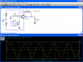
Have a look at the attached circuits. Note the connection of two 9V batteries to obtain + and - supply voltages around ground.
They're both configured as non-inverting amplifiers; the first one has it's gain fixed at 2:1; IE: for given input voltage, it's output is double.
The 2nd one is variable from 1:1 to 100.1:1.
If you look at the output from a "real" 741, you will see a phenomenon known as "phase reversal", "phase inversion" and "lockup" when the gain times input exceeds the capability of the device. Modern op amps have internal circuitry which prevent this.
Audioguru,
While I agree with you as far as AC signals go, that would not help the OP if they were looking at DC levels. I had to assume that:
1) The OP is very new to op amps
2) The circuit needed to be capable of handling anything from a DC level to the op amp's BW limitations (which in the case of the 741 is rather severe, but it's still a good exercise for a beginner. )
3) The OP needed an example of how to create a negative voltage level.
I could have shown the use of a resistive divider across a single 9v battery, but considering the OP's requirement of a 741 demonstration, that wouldn't have left much useable headroom.
Were the 741 an automobile, it would be a rusty 1966 Ford Fairlane with a small straight 6-cylinder engine, manual shift and patched seat covers.
It makes one appreciate the Jaguars and Ferraris available nowadays so much more
 Facebook
 Google
 GitHub
 Linkedin

") )
)


