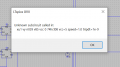
There are so many errors in your basic LTS asc file circuit, the simulation cannot run.
You have 12V signals and 5V logic, why is there 10k source resistance in all the voltage sources??
I will debug it as much as possible and post the result.
E
This is the first time I've worked intensively on something like this. Normally I need this relay "HF356", but since I couldn't find it in the library, I took this one, see below "Relay Library", because the contact configuration is the same (spdt) and I wanted something easy to simulate, since I couldn't find the type I needed for my simulation. I had already posted the data sheet for the HF356 relay here. Thank you for your efforts.
Actually D-Flip Flop is controlled by NI DAQ 6212. I had shown at the very beginning, I think I page 1 my concept here, how I want to realize the whole thing. When i add your example to mine, it always shows errors.
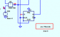
"Try adding .inc 74hct.lib to the circuit." - What do you mean?
Sure... If that's what you meant, I had already said something similar... I am currently working on the development of a complex system that includes a variety of components, including multiplexers, digital and analog signals and an addressable interface. It is important that the circuit is expandable so that more boxes can be connected in the future.
A memory is required to ensure that the addressing of a box is retained when it is selected. Comparators and D flip-flops are used here. These are used to store the states so that the box does not lose its address. The circuit has the task of controlling the relays and switching them on or off so that they can act as switches.
My task also includes recording the switching behavior of the MOSFETs via LabVIEW. I will then write a LabVIEW program to implement this.
I have already done this and it shows other errors. So the circuit should be correct, but I would have liked to have a working simulation. Knowing that the simulation works would also be great.
Hi Man,
I would recommend that you create the LTSpice circuits, step by step, starting say at the Input section of the circuit, rather than the complete circuit.
It will be easier to identify and fix and prove the circuits in a modular way.
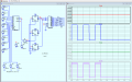
This is what I started doing in the partial debug circuit.
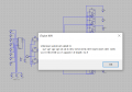
If you get an Error use the mouse cursor and view the extreme bottom left of the LTS window which will display the Node over which the cursor is placed, this will give you an idea of which 'model' is causing a problem.
Post when you are ready a simulation section circuit and, I will try it out.

 Facebook
 Google
 GitHub
 Linkedin