Facebook
 Google
 GitHub
 Linkedin
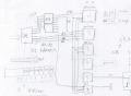
Hello everyone, I'm currently working on a digital circuit design. I'm having trouble figuring out a concept for assembling 8x 1 to 8 demultiplexers in a way that consumes minimal digital outputs. I have an NI-DAQ card with 16 digital IO, and I want to use as few digital outputs from my DAQ card as possible—ideally just around 8 bits to control the demultiplexers. How can I solve this problem? Has anyone built something similar and has a sample circuit ready for me?
8x 1 to 8 Demultiplexers
- Thread starter Mancoba1
- Start date