8A load transistor/FET for 555 output

ebeowulf17

Joined Aug 12, 2014
3,307
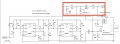
Sorry, still haven't had time to get a really good look at the diode layout, but at first glance it looks like the ones by the top 555 aren't arranged according to the schematic. Maybe start by double checking those.
 

Thread Starter

lvgforums

Joined Jul 12, 2015
51
Here are more pictures. I don't really understand the diodes positioning but I think they are right. remember the first A1B1C1 etc is my "unlock/trigger/jump" row. The yellow wires are jumped in the middle of the board due to wire length issues.


Alec_t

Joined Sep 17, 2013
14,330
I need to ask you about the circuit ownership.
As far as I'm concerned anyone can make what use they like of the circuits I posted in this thread (but note that as they stand the circuits are unsuitable for commercial use in an automotive environment). Check AAC's Terms of Service regarding copyright.
I don't really understand the diodes positioning but I think they are right.
Sadly no. You have two diodes with their anodes connected together at breadboard co-ordinates B1,D1.
Diode D1 is to supply the unlocking +ve pulse to the FET gate. Diode D2 provides a rapid discharge path for C1 when the unlatching pulse goes high, and it clamps the pin 2 voltage to just above the +12V rail.
 

ebeowulf17

Joined Aug 12, 2014
3,307
Ok, finally had time to take a better look...

The two diodes by the top 555 are arranged incorrectly, and several connections down by the MOSFET are also mixed up. Let's just try to get these to all match the schematic.

Near the top 555, one diode should have its anode (unmarked side) in the row with the capacitor leg (row 12, I think.) The cathode (striped side, marked with black in this case) of that same diode should go to the row with your yellow wire, which looks like row 3.

The second diode should have its anode in the row with 555 trigger pin 2 and the other capacitor leg (row 6, I think.) Its cathode should connect to the positive voltage rail.

Meanwhile, a lot of connections down near the MOSFET are wrong. Having looked more closely at earlier pictures, it looks like they never did quite match the schematic, although they were close enough to work for a while. The latest changes are pretty out there. You'll definitely want to get more practice reading schematics and interpreting their connections in the physical world... for now though, I'm going to try making a breadboard drawing for just that section which will hopefully clear things up.

You can go ahead and make the diode changes right away, but you should probably wait on testing the circuit until the MOSFET area is fixed up. I have no idea what it would do in its current configuration. I'll update shortly with the drawing.
 

ebeowulf17

Joined Aug 12, 2014
3,307
Ok, hopefully this does the trick. I think your other MOSFET connections were ok, but everything going on with the gate connection was wrong. Update it to match this and I think you'll be up and running (with the aforementioned diode fixes in as well of course.)

You want to end up with all of the following connected to the gate:
- both diode cathodes (D4 directly and D1 through the long yellow connecting wire)
- Resistor R8
- Capacitor C7

The other sides of C7 and R8 both connect directly to the ground rail.
The other sides of the diodes connect to the unlock signal (which comes in on the leg of C1 opposite the 555 connection) and U2, output (pin 3.)

After all this, we're still missing the D3 addition to the second 555, but that shouldn't matter for testing purposes right now.

555-Door-Unlock_01_bb.png
 

Thread Starter

lvgforums

Joined Jul 12, 2015
51
Hello all, I'm kind of at a standstill without that TVS diode. Plus I don't have a +12V power supply so my 9V batteries keep running out.

Thank you ebeowulf and alec again, that pinout diagram helped. I think it's right now and will take pictures later.

Which one of these do I order? They all have different part numbers. Does digikey charge a lot just for one little thing to ship? My only other choice is waiting 7 days from a random seller on Amazon and $6.00 just for one diode.

http://www.digikey.com/product-search/en?vendor=0&keywords=SMBJ24CA
 
Last edited:

ebeowulf17

Joined Aug 12, 2014
3,307
Does digikey charge a lot just for one little thing to ship?
Can't predict what it will be for you in whatever your location is, but DigiKey orders for me usually ship for around $3.00 via US mail, and although regular 1st class mail makes no promises on speed, I always get the packages two days after I place the order.
 

ebeowulf17

Joined Aug 12, 2014
3,307
Hello all, I'm kind of at a standstill without that TVS diode. Plus I don't have a +12V power supply so my 9V batteries keep running out.
Did you get a chance to try the new wiring layout yet? Does it seem to work as expected? I'd recommend not changing too many things at once, by which I mean it seems like a good idea to get it totally working the way you want on the breadboard before connecting it to the car, just in case something about interfacing with the car throws a monkey wrench in the works!
 

ebeowulf17

Joined Aug 12, 2014
3,307
As for TVS selection, we'll have to wait for Alec's expertise for clarification. Personally, I find surface mount (SMT or SMD) components to be pretty difficult to incorporate into hand made, one-off projects like this (totally different scenario when you get to make custom PCBs.) I couldn't find anything on DigiKey that seemed like a good match in terms of specs, that was currently in stock, and that was sold in through-hole (instead of surface mount) versions.

This search on Mouser yielded what seem like some possible substitutes. All different model numbers but comparable specs as far as I can tell. In the past I've found Mouser shipping to me more expensive than DigiKey, but still probably better than trying to find what you need on Amazon.

Hopefully Alec can provide a better idea of what would make an acceptable substitute. I know there are lots of different types of TVS devices (diodes, varistors, etc.) but I have no idea what the performance considerations are for each.
 

Thread Starter

lvgforums

Joined Jul 12, 2015
51
OK, let's see what he says.

If need to shorten the delay and pulse by a very ,very, very small amount to match the OEM pulse, should I change the caps or the diodes? Or both? I read it's batter to keep capacitors bigger and change resistors, but that's beyond my knowledge. I've seen 555 calculators but I don't know if that applies here since this is a little different.

Also, something for later to simplify, I should just be able to follow the same concepts if I want to combine the 555s into a 556 right? Or will a 556 not work at all for this? I have one sitting here.
 

Alec_t

Joined Sep 17, 2013
14,330
The diodes in the post #87 link are all surface-mount, so not ideal for you.
The TVS diode I specified was chosen fairly arbitrarily, primarily for its operating voltage and because I had a Spice model for it. I'm sure there are many substitutes, for example a varistor such as this one, or one of these. The obvious things to look for are operating voltage and through-hole mounting, but I'm no expert in this field so other suggestions are welcomed.

Re changing the delay and pulse timing, the timing components are C3,C6,C7,R3,R6,R8. I'd leave the caps as is but adjust the resistor values as necessary. Lower resistance = shorter time. C7/R8 stretch the incoming Unlatching pulse duration slightly, C3/R3 set the delay between the first and second pulse, C6/R6 set the second pulse duration.
The 556 will work fine in place of the two 555's.
 
Last edited:

Alec_t

Joined Sep 17, 2013
14,330
I used the values I have now and it's 0.5 seconds, so this calculator can be used if I want to make it 0.4 seconds etc.. ?
If the present resistor value R gives 0.5 sec, then make it R*4/5 to get 0.4 secs. The delay is proportional to the resistance. See if that calculator agrees ;).
 

Thread Starter

lvgforums

Joined Jul 12, 2015
51
I just had an idea - can I skip all this stuff if I just power the main rail (to the 555s) with direct car battery voltage? Or is there still interference and voltage smoothing I have to worry about? I have many free direct +12V lines tapped from the battery into the cabin as I used to have some performance stuff on the car.
 

Attachments

ebeowulf17

Joined Aug 12, 2014
3,307
I just had an idea - can I skip all this stuff if I just power the main rail (to the 555s) with direct car battery voltage? Or is there still interference and voltage smoothing I have to worry about? I have many free direct +12V lines tapped from the battery into the cabin as I used to have some performance stuff on the car.
What else would you have been powering it with? I thought the plan was for there to be 12V power input there to begin with. Pretty sure you need steady 12V power AND those filters.
 

Thread Starter

lvgforums

Joined Jul 12, 2015
51
Received the TVS today. Can resume testing. Will post another board picture shortly.

ebeowulf - what I meant was tapping directly to the battery instead of going through an existing +12V VCC that is probably ran through all sorts of relays and other electronic components in the car.
 

Attachments

Last edited:
Top