8 pin cable dummy load

Thread Starter

Tonyorlo

Joined Jan 30, 2019
6
I hope I am posting this in the right section, if not admins please move to where it needs to be.

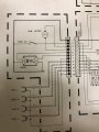
I have a older JVC car receiver with a 8 pin mini din connection for a cd changer. I want to be able to connect a rca device or a 3.5mm device through that connector. The unit will not change over to thag mode unless the cd changer is connected, so I assume it needs to see a load. I do not have the cd changer anymore, this equipment was removed from my truck years ago. I have schematics for the reciever and have been able to locate the L and R audio signals, as well as a 14v and ground connections.

Can anyone help or advise me on how to make a false load so the reciever thinks there is a changer connected still? The L and R signals can just be connected to RCA jacks.

https://www.vintageshifi.com/repertoire-pdf/pdf/telecharge.php?pdf=Jvc-KSRT-414-Service-Manual.pdf
 

RPLaJeunesse

Joined Jul 29, 2018
252
I don't think it will be that easy, looking at page 60 of the above service manual. The receiver communicates with the changer on two serial lines. You would need to build an interface that intercepts commands and provides the needed responses to get the audio path to switch over. The commands and responses are not in the service manual for the receiver. Might be easier to get an old CD changer with a bad mechanism and hack that to provide the audio input, but even that may not work if the changer reports an error and the receiver refuses to switch the audio source.
 

Thread Starter

Tonyorlo

Joined Jan 30, 2019
6
I did catch where the reciever can display an error with the changer. I was hoping it would still allow me to change inputs and play the signals sent to it while showing an error code on the screen. Wishful thinking probably. 2 of the pins land on a processor, which I figure sends the signals from the faceplate to the changer for selecting the cds. I am completly lost on what I would need to do with them, if at anything at all?

I will not be heartbroken if I can’t make this happen. I just wanted to use this receiver because it looks more “period correct” than new ones in my Datsun 280zx.

I have another question, would it be possible to send the signals from a RCA pair through the tape decks output? I do not need the tape deck anymore, but I would probably need to leave a tape in for that input to work.
 

Externet

Joined Nov 29, 2005
2,202
Agree with above comment. A dummy load cable is not a solution, as there is a 2 way data communication wired to tell track, number of discs, perhaps titles to display; and play/skip/next disc/eject... commands.
The way I did it is tapping the L,R inputs to the audio management integrated circuit pins to implement such auxiliar input with the 3.5mm plug. I used the unwanted 'tape' selection on the front panel to enable the added auxiliar input. But may need to trick 'cassette inserted' signal too. AM radio is another simpler option to the audio path. Selecting 'AM' enables the RCA pair.
IC931 pins 16,17 is also a good place to enter from a 3.5mm cancelling jack.
 
Last edited:

Thread Starter

Tonyorlo

Joined Jan 30, 2019
6
Well that’s good news. I’d rather not leave a tape in at all times, I will have to look but maybe I could jumper something out internally to trick it into thinking there is a tape Inserted?

Say I went this route with the tape deck. I would want to use pins 3 and 14 from IC921 for the L and R correct? Very dumb question, but where will I land the grounds for the pairs? I assume the positive lands on the IC921.

If I decided to use the AM spot and I land them on 16 and 17 of IC931, will that effect me using the FM of the radio? When I am on the AM it won’t still try to play those signals? Will I need to lift the current wires from 16 and 17 and land the RCA wires there? It just looks like thag is where AM and FM both land.

Sorry for the stupid questions, I am a novice and am still learning.
 
Last edited:

Thread Starter

Tonyorlo

Joined Jan 30, 2019
6
Sorry for the multiple posts. I removed the tape player and closed the tape in switch so I can now select tape mode. It just continuously scans for a tape. If I put the display on the clock I will never know the difference.

I just now need some help correctly wiring the rca to the amp. Can anyone verify the pin locations and the grounds?
 

Externet

Joined Nov 29, 2005
2,202
Do not use the tape heads for input. Use the preamplified signal at a later stage to inject the new auxiliar jack or plug, either RCA or 3.5mm.
Better use a 3.5mm cancelling jack -on the front panel?- and a male to male 3,5mm cable to the new source.
Jumping the tape-is-in switch may turn the tape motor on, and start clicking/ejecting as there is no tape movement sensing. Depends the design of your unit. Tinker with it to learn how it behaves. Perhaps the motor can be disconnected. Explore inner workings. Perhaps disconnecting the whole CP503 plug shown will work; as if the unit was manufactured without a cassette option...
Ground goes to common chassis traces. CP503 1,12. Some schematic nodes will work with DC superimposed to audio, that is why capacitors are in series to signal paths. Make sure your audio source has no DC.
"RCA to amp" ¿?¿?¿? What amp? The receiver unit ?
Using the AM path should be done by lifting the pins of the IC that takes AM so there will be no AM playing while the auxiliar is fed. Study the schematic with patience.
 
Last edited:

Thread Starter

Tonyorlo

Joined Jan 30, 2019
6
I pulled the tape deck and just tried landing the leads for the 3.5 on cp501. It would still switch modes with the deck out, but I was don’t getting any sound from the speakers.

I have looked the the tuner section, but I don’t see how I can use the AM signal without looking FM as well? How I read it is that the FM and AM signal are a single channel. I can trace them to the IC but and not sure where to go from there.
 

Externet

Joined Nov 29, 2005
2,202
There is many ways to do it; IC921 pins 3,14 on Fig 9.1 and 10.4 are the correct points to feed your new-extra AUX signal instead of the tape deck.
IC931 pins 15,18 on figure 9.1 and 10.4 are the CD audio paths.
ICL, ICR = input cassette left, input cassette right. But did not follow how such 'tape' paths are selected by the microcontroller (Pin 50, IC701).
(As the new added AUX input better be injected before the volume control IC931 output chip.)


There is a weird way I have never tried:
Feed your new AUX L,R into RCA jacks J961 Lfront, Rfront output. Check what happens at several input selections and come back with observations. Perhaps I will learn something from this. Disconnect/lift anode pin of D151 if necessary to prevent Q151, Q152 from muting/grounding those L,R output paths that will be now used as inputs while tuned on an empty radio frequency or no CD, or no tape. But will need volume controlling at the added AUX.

The schematics having split pages make me difficult to see/follow better on screen. Print and join to see/follow, my printer is kaput.
Pin 12 of IC921 has to be the key ! Probe DC levels there (CP501 pin 16 MODE) to see what is going on when tape/radio is selected.

A cancelling jack works as :


Providing the AUX audio cable into your chip inputs when plugged, instead of the normal path restored when unplugged. Like a double pole double throw circuit.
 
Top