8 Bit Shift Register with PIC16F628A

Thread Starter

beeson76

Joined Apr 19, 2010
211
I know this is a long shot:)

I have a TPIC6595 8 Bit Shift Register on a Board that is "connected" to a PIC16F628A Microchip.

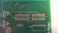
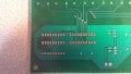
Please see the following pictures.

Here are the connections from the Pic to the Shift Register

RA1 goes to RCK
RA0 goes to SRCLR
RA2 goes to SRCK
RA3 goes to G
RA4 goes to SER IN

In the pictures below, the shift register goes on U2 and the Microchip goes on U1.

And then the the 8 Drain from the Shift Register are all connected to corresponding relays which in turn are connected to motors.

You wont like it very much but I don't have a schematic of the circuit but I can certainly provide pictures, and maybe draw up a crude schematic in autocad or something.

As far as the inputs I have 7 inputs (PORTB) on the Microchip that is connected to a controller that eventually controls the motors. For example, you hit Switch1, and the microchip recognizes the button press and sends a control to the shift register which in turns sends control to the relay for Motor1. (I am assuming that is how is works, because I don't really know anything about shift registers)

So now to the problem. I don't have any code for the Microchip. I can program the code in C, and I already have the code written to recognize the button press and now I am stuck on how I send it to the shift register. I did some reading on the internet, and I am getting more confused, the more I read. I just need some help in being pointed in the right direction, such as how to write the code.

Any help in getting pointed in the right direction would be greatly appreciated:)
 

Attachments

Last edited:

MMcLaren

Joined Feb 14, 2010
861
It sounds like you're looking for a function like this, maybe?

Rich (BB code):
   #define dat porta.4          // RA4 = SER(in)
   #define clk porta.2          // RA2 = SRCK
   #define lat porta.1          // RA1 = RCK

   void shiftout(char work)
   { unsigned char i;           //
     for(i=8; i>0; i--)         // load TPIC6C595 shift register
     { dat = 0; clk = 0;        // preset dat and clk pins
       if(work.7) dat = 1;      // set dat to '1' for a '1' bit
       clk = 1;                 // clock out the bit
       work <<= 1;              // prep for next bit
     }                          //
     lat = 1; lat = 0;          // copy SR bits onto the outputs
   }                            //
You could probably tie the clear pin to VCC and the output enable pin to ground, unless you have some other operations in mind for those pins.

Regards, Mike
 

Markd77

Joined Sep 7, 2009
2,806
If it matters what happens to the relays as the PIC is first powered up / reset, you can connect the output enable to 5V with a 10K resistor and then pull it low with a pin once valid data has been shifted in.
Here's some assembler which is fairly well optimised for speed (assumes there are no other outputs on PORTA, and it's missing the storage register pulse).
Rich (BB code):
    clrf PORTA
    clrw
    btfsc INDF, 7
    movlw 2
    movwf PORTA        ;set or clear PORTA, 1 (data)
    andlw 1
    movwf PORTA        ;set PORTA, 0 (clock)
    
    clrf PORTA
    clrw
    btfsc INDF, 6
    movlw 2
    movwf PORTA        ;set or clear PORTA, 1 (data)
    andlw 1
    movwf PORTA        ;set PORTA, 0 (clock)
    
    clrf PORTA
    clrw
    btfsc INDF, 5
    movlw 2
    movwf PORTA        ;set or clear PORTA, 1 (data)
    andlw 1
    movwf PORTA        ;set PORTA, 0 (clock)
    
    clrf PORTA
    clrw
    btfsc INDF, 4
    movlw 2
    movwf PORTA        ;set or clear PORTA, 1 (data)
    andlw 1
    movwf PORTA        ;set PORTA, 0 (clock)
    
    clrf PORTA
    clrw
    btfsc INDF, 3
    movlw 2
    movwf PORTA        ;set or clear PORTA, 1 (data)
    andlw 1
    movwf PORTA        ;set PORTA, 0 (clock)
    
    clrf PORTA
    clrw
    btfsc INDF, 2
    movlw 2
    movwf PORTA        ;set or clear PORTA, 1 (data)
    andlw 1
    movwf PORTA        ;set PORTA, 0 (clock)
    
    clrf PORTA
    clrw
    btfsc INDF, 1
    movlw 2
    movwf PORTA        ;set or clear PORTA, 1 (data)
    andlw 1
    movwf PORTA        ;set PORTA, 0 (clock)
    
    clrf PORTA
    clrw
    btfsc INDF, 0
    movlw 2
    movwf PORTA        ;set or clear PORTA, 1 (data)
    andlw 1
    movwf PORTA        ;set PORTA, 0 (clock)
 

MMcLaren

Joined Feb 14, 2010
861
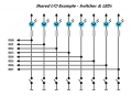
You could probably have some fun with this project. For example, if you're using the push button switches to emulate toggle switches (press to toggle a motor from on-to-off or from off-to-on), each pin can support both a switch and an LED, like this;


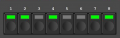
There are some nice lighted push button switches available. I used some from Mouser in the past that looked like this;


Software for debouncing and reading the switches, as well as driving the LEDs, is relatively simple. Here's a small (untested) example program using the free/lite version of BoostC;

Cheerful regards, Mike

Rich (BB code):
/********************************************************************
 *                                                                  *
 *  Project: Relay Demo                                             *
 *   Source: Relay_Demo.c                                           *
 *   Author: Mike McLaren, K8LH                                     *
 *     Date: 30-Jul-12                                              *
 *  Revised: 30-Jul-12                                              *
 *                                                                  *
 *  16F628A + TPIC6C595 Eight Channel Relay Demo                    *
 *                                                                  *
 *                                                                  *
 *      IDE: MPLAB 8.84 (tabs = 4)                                  *
 *     Lang: SourceBoost BoostC v7.05, Lite/Free version            *
 *                                                                  *
 ********************************************************************/

  #include <system.h>

  #pragma DATA _CONFIG, _LVP_OFF&_MCLRE_OFF&_WDT_OFF&_INTOSC_OSC_NOCLKOUT

  #pragma CLOCK_FREQ 4000000      // 4-MHz Internal Oscillator

//--< function prototypes >------------------------------------------
//--< typedef and defines >------------------------------------------

  #define clk porta.2           // RA2 -> SCK (serial clock)
  #define dat porta.4           // RA4 -> SER (data input)
  #define lat porta.1           // RA1 -> RCK (data latch)

//--< variables >----------------------------------------------------

  char swnew = 0;               // 
  char swold = 0;               // switch state latch
  char flags = 0;               // toggle state flags
  
//--< functions >----------------------------------------------------

/********************************************************************
 *  main init                                                       *
 ********************************************************************/
 
 void main()
 { 
   cmcon = 0x07;                // comparator off for digital I/O
   trisb = 0b11111111;          // set all pins to inputs
   trisa = 0b00000000;          // set all pins to outputs
   portb = 0b00000000;          // set all output latches to '0'
   porta = 0b00000000;          // set all output latches to '0'

/********************************************************************
 *  main loop                                                       *
 ********************************************************************/

   while(1)
   { delay_ms(25);              // 25-msec sample intervals

  /*                                                                *
   *  Lighted Push Button Switches (emulated toggle switches)       *
   *                                                                *
   *  swnew  ____---____-----___   sample active lo switches        *
   *  swold  _____---____-----__   switch state latch               *
   *  swnew  ____-__-___-____-__   changes, press or release        *
   *  swnew  ____-______-_______   filter out 'release' bits        *
   *  flags  _____-------_____--   toggle flag bits for main        *
   *  trisb  -----_______-----__   toggle tris bits for LEDs        *
   *                                                                */
     trisb = 0b11111111;        // set all portb to inputs
     swnew = ~portb;            // sample active lo switches
     swnew ^= swold;            // changes, press or release
     swold ^= swnew;            // update switch state latch
     swnew &= swold;            // filter out 'release' bits
     flags ^= swnew;            // toggle flag bits for main
     portb = 0b00000000;        // clear portb output latches
     trisb ^= flags;            // light only active sw LEDs

  /*                                                                *
   *  update TPIC6C595 outputs after any switch state change        *
   *                                                                */
     if(swnew)                  // if any "new press" bits
     { char mask = 0b10000000;  // 
       while(mask)              // shift out 8 bits
       { clk = 0; dat = 0;      //
         if(flags & mask)       // if a '1' bit
           dat = 1;             // set <dat> pin
         clk = 1;               // clock out the <dat> bit
         mask >>= 1;            // shift mask for next bit
       }                        //
       lat = 1; lat = 0;        // copy SR bits onto outputs
     }                          //
   }                            //
 }                              //
 

Attachments

Last edited:

Thread Starter

beeson76

Joined Apr 19, 2010
211
Wow:), thanks guys for the nice replies.

My programming will be really basic, and after I get the concept I will put things in functions etc. Here is what I have right off. It will require a lot more work, but Im just wanting to get some of your opinions.

Here is my code. It is not compiled yet, and therefore untested. I think it is pretty well commented out, so you should be able to figure out:):)

Rich (BB code):
/////////////////////////////////////////////////////////////////////////////////////////////////////////////////////////////////
//
//This program controls a Matrix Switch.  The Switch consists of 2 columns and 5 rows.
//Whenever a switch is pushed it simply turns on a motor.
//The PIC16F628A Microcontroller from Microchip is being used.  
//Also the TPIC6595N 8 Bit Shift Register is being used.  It will be controlled by the PIC16F628A chip. 
//
//RA1 goes to RCK on TPIC6595N
//RA0 goes to SRCLR ""
//RA2 goes to SRCK ""
//RA3 goes to G ""
//RA4 goes to SER IN ""
//
//As I learn more about the TPIC6595N I will write more about it here:)
//
/////////////////////////////////////////////////////////////////////////////////////////////////////////////////////////////////
#define _LEGACY_HEADERS

#include <htc.h>


#define dat 		    RA4     	// RA4 = SER(in)
#define clk 		    RA2    	 	// RA2 = SRCK
#define lat 			RA1         // RA1 = RCK

#define	COL_1			RB0
#define COL_2			RB1
#define	ROW_1			RB3
#define ROW_2			RB4
#define	ROW_3			RB5
#define	ROW_4			RB6
#define ROW_5			RB7

#define  DelayS(T)		{unsigned char i; for (i = 0; i < T * 10; i++) __delay_ms(100);}	//Delay Macro
#define  _XTAL_FREQ				4000000								//Needs to be set for __delay_ms


//Master Clear Reset enabled & Internal RC No Clock & Watchdog Timer Disable & Power Up Timer On & Brown Out Reset Disabled &
// Low Voltage Porgramming Disabled & Code Unprotect
__CONFIG (MCLREN & INTIO & WDTDIS & PWRTEN & BORDIS & LVPDIS & UNPROTECT);

main()
{
	
PORTA = 0x00;										//PORTA is cleared and set low
PORTB = 0xFF;										//(0b11111111 binary) (0xFF hex)--ROWS set to HIGH, COLUMNS set to HIGH  
													//PORTB7:B0 is set to high,high,high,high,high,high,high,high)
													
TRISA = 0x00;										//Set PORTA to outputs for LCD--RA1, RA2, RA4 are Control lines for LCD

TRISB = 0x7C;										//(0b01111100 binary) (0x7C hex)--ROWS set to INPUT, COLUMNS set to OUTPUT
													//PORTB7:B0 is set to output,input,input,input,input,input,output,output,
													//ROWS set to INPUT

OPTION = 0b01010101;								//OPTION REG
													//xbxxxxx101  1:64
													//xbxxxx0xxx  Prescaler set to Timer0
													//xbxxx1xxxx  (T0SE) set to Increment on high-to-low transition on T0CKI pin
													//xbxx0xxxxx  (T0CS) Internal instruction cycle clock
													//xbx1xxxxxx  (INTEDG) Interrupt on rising edge of INT pin
													//xb0xxxxxxx  (RBPU) PORTB pull-ups are enabled by individual PORT latch values
RBPU = 0;											//Don't think I need this, but to be safe...PORTB Weak Internal Pullups enabled
WPUB0 = 0;											//COL_1 Weak pullup is individually DISABLED--OUTPUT 
WPUB1 = 0;											//COL_2 Weak Pullup is inidivdually DISABLED--OUTPUT
WPUB2 = 0;											//Not being used...Weak Pullup is individually DISABLED
WPUB3 = 1;											//ROW_1 Weak Pullup is individually ENABLED--INPUT
WPUB4 = 1;											//ROW_2 Weak Pullup is individually ENABLED--INPUT
WPUB5 =	1; 											//ROW_3 Weak Pullup is individually ENABLED--INPUT
WPUB6 = 1;											//ROW_4 Weak Pullup is individually ENABLED--INPUT
WPUB7 = 0;											//COL_3 Weak Pullup is individually DISABLED--INPUT


char i;


while (1)
	{
		COL_1 = 0;									//COLUMN 1 is set LOW
		if (ROW_1 == 0)								//and If ROW 1 is LOW...
			{
				for (i = 8; i > 0; i--)         	// load TPIC6C595 shift register
     					{ 
	     					dat = 0; 
	     					clk = 0;        		// preset dat and clk pins
       						if(work.7) 
       							{
	       							dat = 1;      	// set dat to '1' for a '1' bit
	       						}
       						clk = 1;               	// clock out the bit
       						work <<= 1;            	// prep for next bit
     					}                         	//
     					lat = 1; 
     					lat = 0;          			// copy SR bits onto the outputs
			}
				
		if (ROW_2 == 0)								//if ROW 2 is LOW...
			{
				for (i = 8; i > 0; i--)         	// load TPIC6C595 shift register
     					{ 
	     					dat = 0; 
	     					clk = 0;        		// preset dat and clk pins
       						if(work.7) 
       							{
	       							dat = 1;      	// set dat to '1' for a '1' bit
	       						}
       						clk = 1;               	// clock out the bit
       						work <<= 1;            	// prep for next bit
     					}                         	//
     					lat = 1; 
     					lat = 0;          			// copy SR bits onto the outputs										
			}	
		if (ROW_3 == 0)								//If ROW 3 is LOW
			{
				for (i = 8; i > 0; i--)         	// load TPIC6C595 shift register
     					{ 
	     					dat = 0; 
	     					clk = 0;        		// preset dat and clk pins
       						if(work.7) 
       							{
	       							dat = 1;      	// set dat to '1' for a '1' bit
	       						}
       						clk = 1;               	// clock out the bit
       						work <<= 1;            	// prep for next bit
     					}                         	//
     					lat = 1; 
     					lat = 0;          			// copy SR bits onto the outputs										
			}
		if (ROW_4 == 0)								//If ROW 4 is LOW
			{
				for (i = 8; i > 0; i--)         	// load TPIC6C595 shift register
     					{ 
	     					dat = 0; 
	     					clk = 0;        		// preset dat and clk pins
       						if(work.7) 
       							{
	       							dat = 1;      	// set dat to '1' for a '1' bit
	       						}
       						clk = 1;               	// clock out the bit
       						work <<= 1;            	// prep for next bit
     					}                         	//
     					lat = 1; 
     					lat = 0;          			// copy SR bits onto the outputs										
			}
		if (ROW_5 == 0)								//If ROW 4 is LOW
			{
				for (i = 8; i > 0; i--)         	// load TPIC6C595 shift register
     					{ 
	     					dat = 0; 
	     					clk = 0;        		// preset dat and clk pins
       						if(work.7) 
       							{
	       							dat = 1;      	// set dat to '1' for a '1' bit
	       						}
       						clk = 1;               	// clock out the bit
       						work <<= 1;            	// prep for next bit
     					}                         	//
     					lat = 1; 
     					lat = 0;          			// copy SR bits onto the outputs										
			}
			
		COL_1 = 1;									//COLUMN 1 is set HIGH again
		COL_2 = 0;									//COLUMN 2 is set LOW
		if (ROW_1 == 0)								//and If ROW 1 is LOW...
			{
				for (i = 8; i > 0; i--)         	// load TPIC6C595 shift register
     					{ 
	     					dat = 0; 
	     					clk = 0;        		// preset dat and clk pins
       						if(work.7) 
       							{
	       							dat = 1;      	// set dat to '1' for a '1' bit
	       						}
       						clk = 1;               	// clock out the bit
       						work <<= 1;            	// prep for next bit
     					}                         	//
     					lat = 1; 
     					lat = 0;          			// copy SR bits onto the outputs										
			}
				
		if (ROW_2 == 0)								//if ROW 2 is LOW...
			{
				for (i = 8; i > 0; i--)         	// load TPIC6C595 shift register
     					{ 
	     					dat = 0; 
	     					clk = 0;        		// preset dat and clk pins
       						if(work.7) 
       							{
	       							dat = 1;      	// set dat to '1' for a '1' bit
	       						}
       						clk = 1;               	// clock out the bit
       						work <<= 1;            	// prep for next bit
     					}                         	//
     					lat = 1; 
     					lat = 0;          			// copy SR bits onto the outputs										
			}
		if (ROW_3 == 0)								//If ROW 3 is LOW
			{
				for (i = 8; i > 0; i--)         	// load TPIC6C595 shift register
     					{ 
	     					dat = 0; 
	     					clk = 0;        		// preset dat and clk pins
       						if(work.7) 
       							{
	       							dat = 1;      	// set dat to '1' for a '1' bit
	       						}
       						clk = 1;               	// clock out the bit
       						work <<= 1;            	// prep for next bit
     					}                         	//
     					lat = 1; 
     					lat = 0;          			// copy SR bits onto the outputs										
			}
		if (ROW_4 == 0)								//If ROW 4 is LOW
			{
				for (i = 8; i > 0; i--)         	// load TPIC6C595 shift register
     					{ 
	     					dat = 0; 
	     					clk = 0;        		// preset dat and clk pins
       						if(work.7) 
       							{
	       							dat = 1;      	// set dat to '1' for a '1' bit
	       						}
       						clk = 1;               	// clock out the bit
       						work <<= 1;            	// prep for next bit
     					}                         	//
     					lat = 1; 
     					lat = 0;          			// copy SR bits onto the outputs										
			}
		if (ROW_5 == 0)								//If ROW 4 is LOW
			{
				for (i = 8; i > 0; i--)         	// load TPIC6C595 shift register
     					{ 
	     					dat = 0; 
	     					clk = 0;        		// preset dat and clk pins
       						if(work.7) 
       							{
	       							dat = 1;      	// set dat to '1' for a '1' bit
	       						}
       						clk = 1;               	// clock out the bit
       						work <<= 1;            	// prep for next bit
     					}                         	//
     					lat = 1; 
     					lat = 0;          													
			}
		COL_2 = 1;										}
}
Any help is greatly appreciated very much. I certainly appreciate it.
 

takao21203

Joined Apr 28, 2012
3,702
Rich (BB code):
dat = 0; 
	     					clk = 0;        		// preset dat and clk pins
       						if(work.7) 
       							{
	       							dat = 1;      	// set dat to '1' for a '1' bit
	       						}
       						clk = 1;               	// clock out the bit
       						work <<= 1;
Rich (BB code):
clk=0;work<<=1;dat=CARRY;clk=1;
 

MMcLaren

Joined Feb 14, 2010
861
hi beeson76,

A couple questions, please? How are you using ten switches with only eight outputs? How do you want the switches to operate the motors? Do you only want a motor to stay on as long as a switch is being held pressed?
 

Thread Starter

beeson76

Joined Apr 19, 2010
211
Thanks for your replies. The controller has 10 buttons. It is in a matrix switch...2 rows and 5 columns. I would like the motors to stay when you press the button, and keep it held down, and then go off when the button is depressed.

Here is how I am programming the matrix switch, there could probably be better code for it, but I want to keep it simple at first.

I am bringing my pin low for my column first, then I am scanning for any of my rows to go low. When a pin goes low, the program is suppose to read it:) and then keep it held low until it is released.

Then I am bringing my pin high on my column, and then it passes on to the pin for my second column.

It keeps scanning like this until a button is pressed...or suppose to anyway:)

I really do appreciate the help guys. I love this forum.
 

MMcLaren

Joined Feb 14, 2010
861
I'm sorry but I don't quite understand. You want a motor to come on when it's switch is pressed and then go off when the switch is depressed (???). Did you mean to say the motor would go off when the switch was released?

Also, you didn't say how you intend to use ten switches for eight outputs.
 

Thread Starter

beeson76

Joined Apr 19, 2010
211
No thats fine:)

I have 7 pins being used on my PORTB. 2 Pins on being used for my Columns on my matrix switch and 5 pins are being used for my Rows on my switch.

Yes when a button is pressed and continued to be pressed, I would like the motor to come on and stay on. Then when the button is let go, I would like the motor to go off.

As far as the chip controlling the 8 bit shift register, I have no idea how it "communicates" with the chip except for the pins that I traced down. They mentioned in the first post. I would like to know the sequence of the "communication" between the chip and shift register, such as do you have to bring something high, write the bits, and then bring it low to send it, and then clear the register, for the next set of bits.

There are a total of 4 motors--each have a set of relays (2 relays per motor) for each motor. One relay controls the up function of the motor, and the other relay controls the down function of the motor. 2 buttons on the control, control 2 motors.

I think I understand now how you were confused:) I wasnt making myself clear at all. I left out a lot of details:)

I will try to clarify things a little bit. 4 sets of buttons on the control each control a motor...each set has an up and down button--thus you have 8 buttons. The 9th and 10 buttons control 2 motors in unison.

I hope this helps. Please ask if you still need help with the layout. Sorry for the missed details:)
 

MMcLaren

Joined Feb 14, 2010
861
That seems a bit more complicated. For example, will you need logic to prevent both the "up" and "down" relays for any particular motor from actuating at the same time?
 

Thread Starter

beeson76

Joined Apr 19, 2010
211
Yes I will.

I have a circuit board, with all components. I have the original code for the PIC but for some reason, it always locks up the relays after using it a little bit. The only way of getting it to shut down is unplug it, listen for the relay to unlatch and wait a few seconds even after that. After plugging it back in it will work normally until it happens again:)

Something is causing the whole circuit to lock up with relays latched, and I am trying to check to see if it is the programming. The programming is using the CCS Compiler which Im really not familiar to. But I have an old version (2007) laying around. Here is the original code for it.
 

Thread Starter

beeson76

Joined Apr 19, 2010
211
Rich (BB code):
/* Pre-processor **************************************************************/
#include "16F628.h"		// Header file.
#include <stdlib.h>


#case							// Makes CCS case sensative.
#use standard_io(A)     

#define ON 1				// These are useful.
#define OFF 0
#define bool short int	// 'Boolean' and "short int" take too long to type!

#define SRCLR  PIN_A0   // Clears input shift register (active low).
#define RCK    PIN_A1   // Sends shift register data to outputs of device.
#define SRCK   PIN_A2   // Shift register clock (advances serial data on L-to-H).
#define G      PIN_A3   // Enable outputs of shift register.
#define SIN    PIN_A4   // Serial data input (I/O must have a pull-up resistor).

/* Global Variables and Setup**************************************************/
struct pendant_map {		// Defines the pendant port.
	bool col_1;          // Up
	bool col_2;          // Down
	bool unused_col_3;
	int  keys : 5;       // Head, Foot, Bed, Seat, Trend, Chair.
}pendant;

#byte pendant = 6		   // To port B.

struct function {		// Maps the function to a port pin.
	bool hu;
	bool hd;
	bool fu;
	bool fd;
	bool bu;
	bool bd;
	bool t;
	bool tr;
	bool su;
	bool sd;
};

struct scan {		// Holds the information grabbed from the port.
	int in : 5;
	int unused : 3;
};

struct key {		// Used to decode the individual port pins.
	bool h;
	bool f;
	bool b;
	bool t;
	bool s;
   bool un1;
   bool un2;
   bool un3;
};

union combine {	// See above 2 blocks.
  	struct scan a;
   struct key b;
};

union mix{	// Used to convert up/down to one variable.
	struct function data;
   long	ldata;
};

int const PRESCALE = 13;	// Timer0 preset value. For perfect 4MHz (maybe).
int go_thous = 0;				// For main process loop entry.
int to_out = 0;            // Data that is sent to 6595 IC.

struct scan up;	      // Holds pendant up data 'up.in'.
struct scan dn;         // Holds pendant dn data 'dn.in'.

union mix info;			// This is 2 pendant data values converted to 1 long.
long deb_info;				// Use as temp storage to debounce buttons in 'isr'.
union mix use_info;		// Actual modified pendant data to use.

/* Function declarations ******************************************************/
void setup_io(void);			// Sets up all I/O ports.
void start_rtcc(void);		// Sets up the rtcc counter.
void convert(void);			// Convert 2 pendant data values to 1 long.
void check_input(void);		// Enforces buttons pressed follow rules.
void motor_timers(void);	// Sets "change of direction" timers.
void process_state(void);	// Determines outputs for running motors.
void rtcc_isr(void);			// Interrupt service routine.
void make_it_so(void);     // Output to motors.


// Main ***********************************************************************

main() {
	setup_io();
	start_rtcc();

	while(TRUE) {
		if(go_thous){			// This variable set in isr.
			go_thous = 0;

			check_input();
			motor_timers();
			process_state();
			make_it_so();
		}
	}
return 0;
}

// Function definitions ********************************************************

void setup_io(void) {
   set_tris_b(248);				// 1-input, 0-output. All out.
   port_b_pullups(TRUE);		// Use internal pullups.
   output_high(G);         // Turns off outputs.
   output_low(SRCLR);    // Clear input register.
   output_high(SRCLR);     // Input register back on.
   output_low(SRCK);     // Set clock input low.
   output_low(RCK);      // Set sr clock low.
   output_low(SIN);
}

void start_rtcc(void) {
	setup_counters(RTCC_INTERNAL, RTCC_DIV_4);
	set_rtcc(PRESCALE);			// Tunes the actual time to overflow.
	enable_interrupts(INT_RTCC);
	enable_interrupts(GLOBAL);
}

#int_rtcc		// RTCC interrupt subroutine.
rtcc_isr(void) {

	static int debounce = 0;		// Debouncing flag.
	int const DEBOUNCE_TIME = 5;	// Amount X state_mach(max n+1) = milliseconds.
	static int debounce_ctr = 0;	// Duh!
	static int state_mach = 0;		// Usefull for switch/case block.

	set_rtcc(PRESCALE);				// Restart with prescale value (~ 1mS).
  	go_thous = 1;						// For section of "main loop" entry.

	switch(state_mach) {
		case 0:
			pendant.col_1 = 0;		// Set up column low to check pendant. 
			state_mach = 1;
			break;
		case 1:
			up.in = ~pendant.keys;	// Pullups used so ~port to get a high value
			state_mach = 2;			// on the button pressed.
			break;
		case 2:
			pendant.col_1 = 1;		// Change to scan down column.
			pendant.col_2 = 0;
			state_mach = 3;
			break;
		case 3:
			dn.in = ~pendant.keys;	// Same as above.
			state_mach = 4;
			break;
		case 4:
			pendant.col_2 = 1;		// Restore down column to 'high'.
			state_mach = 5;
        	convert();					// Convert the data to a single long.
			break;
		case 5:
			if(debounce){
				if(--debounce_ctr == 0){	// Only do work if debounce completed.
					debounce = OFF;
					if(info.ldata == deb_info) {	// If button still pressed.
						use_info.ldata = deb_info;	// Keep good data.
               }
				}
			}
			else {
            // Or if key changed.
				if(info.ldata != use_info.ldata){
					deb_info =  info.ldata;				// Save, to test it later.
					debounce_ctr = DEBOUNCE_TIME;		// Reset debounce timer.
					debounce = ON;							// Start the timer.
				}
			}
			state_mach = 0;
			break;
		default:
			state_mach = 0;
			break;
	}

return 0;
}

void convert() {
   union combine work;	// Used to decode functions in the input data.

   info.ldata = 0;		// Start with no data in the holder.
   work.a.in = up.in;	// Put in up data.
   if(work.b.h)
   	info.data.hu = ON;
   if(work.b.f)
   	info.data.fu = ON;
   if(work.b.b)
   	info.data.bu = ON;
   if(work.b.t)
   	info.data.t = ON;
   if(work.b.s)
   	info.data.su = ON;

   work.a.in = dn.in;	// Repeat above for down side.
   if(work.b.h)
   	info.data.hd = ON;
   if(work.b.f)
   	info.data.fd = ON;
   if(work.b.b)
   	info.data.bd = ON;
   if(work.b.t)
   	info.data.tr = ON;
   if(work.b.s)
   	info.data.sd = ON;
}

void check_input(void) {
	if(use_info.data.hu && use_info.data.hd)	// Up/dn can never run together.
		use_info.data.hu = 0;
	if(use_info.data.fu && use_info.data.fd)
		use_info.data.fu = 0;
	if(use_info.data.bu && use_info.data.bd)
		use_info.data.bu = 0;
	if(use_info.data.t && use_info.data.tr)
		use_info.data.tr = 0;
	if(use_info.data.su && use_info.data.sd)
		use_info.data.su = 0;

	// Place these in the order of precedence. Trend is master.
	if(use_info.data.t) {	
   	use_info.ldata = 0;
		use_info.data.t = ON;
	}
	if(use_info.data.tr) {
   	use_info.ldata = 0;
		use_info.data.tr = ON;
	}
	if(use_info.data.sd) {
   	use_info.ldata = 0;
		use_info.data.sd = ON;
	}
	if(use_info.data.su) {
   	use_info.ldata = 0;
		use_info.data.su = ON;
	}
}
 

Thread Starter

beeson76

Joined Apr 19, 2010
211
Rich (BB code):
void motor_timers(void) {

	static struct function delays;	// Delay flags.

	static long hd_ctr = 0;		// Counters for up/dn delays.
	static long hu_ctr = 0;
	static long fd_ctr = 0;
	static long fu_ctr = 0;
	static long bd_ctr = 0;
	static long bu_ctr = 0;
	static long t_ctr = 0;
	static long tr_ctr = 0;
	static long su_ctr = 0;
	static long sd_ctr = 0;

	static union mix last;	// Save to compare to button for timers.

	// Start change of direction delay timers if needed.
	// If dn is off but was on, start the delay for up. etc...
	if(!use_info.data.bd && last.data.bd) {
		delays.bd = ON;
		bd_ctr = 750;
	}
	if(!use_info.data.bu && last.data.bu) {
		delays.bu = ON;
		bu_ctr = 750;
	}
	if(!use_info.data.fd && last.data.fd) {
		delays.fd = ON;
		fd_ctr = 750;
	}
	if(!use_info.data.fu && last.data.fu) {
		delays.fu = ON;
		fu_ctr = 750;
	}
	if(!use_info.data.hd && last.data.hd) {
		delays.hd = ON;
		hd_ctr = 750;
	}
	if(!use_info.data.hu && last.data.hu) {
		delays.hu = ON;
		hu_ctr = 750;
	}
	if(!use_info.data.t && last.data.t) {
		delays.t = ON;
		t_ctr = 750;
	}
	if(!use_info.data.tr && last.data.tr) {
		delays.tr = ON;
		tr_ctr = 750;
	}
	if(!use_info.data.su && last.data.su) {
		delays.su = ON;
		su_ctr = 750;
	}
	if(!use_info.data.sd && last.data.sd) {
		delays.sd = ON;
		sd_ctr = 750;
	}

	// This section prevents a direction change on the motors too quickly.
	// Count down until opposite function can be used.
	if(delays.fd) {
		if(--fd_ctr == 0)
			delays.fd = OFF;
		else {
			use_info.data.fu = OFF;
			use_info.data.su = OFF;
		}
	}
	if(delays.fu) {
		if(--fu_ctr == 0)
			delays.fu = OFF;
		else {
			use_info.data.fd = OFF;
			use_info.data.sd = OFF;
		}
	}
	if(delays.hd) {
		if(--hd_ctr == 0)
			delays.hd = OFF;
		else {
			use_info.data.hu = OFF;
			use_info.data.su = OFF;
		}
	}
	if(delays.hu) {
		if(--hu_ctr == 0)
			delays.hu = OFF;
		else {
			use_info.data.hd = OFF;
			use_info.data.sd = OFF;
		}
	}
	if(delays.bd) {
		if(--bd_ctr == 0)
			delays.bd = OFF;
		else {
			use_info.data.bu = OFF;
			use_info.data.t = OFF;
			use_info.data.tr = OFF;
			use_info.data.su = OFF;
			use_info.data.sd = OFF;
		}
	}
	if(delays.bu) {
		if(--bu_ctr == 0)
			delays.bu = OFF;
		else {
			use_info.data.bd = OFF;
			use_info.data.t = OFF;
			use_info.data.tr = OFF;
			use_info.data.su = OFF;
			use_info.data.sd = OFF;

		}
	}
	if(delays.t) {
		if(--t_ctr == 0)
			delays.t = OFF;
		else {
			use_info.data.tr = OFF;
			use_info.data.bd = OFF;
			use_info.data.bu = OFF;
			use_info.data.su = OFF;
			use_info.data.sd = OFF;
		}
	}
	if(delays.tr) {
		if(--tr_ctr == 0)
			delays.tr = OFF;
		else {
			use_info.data.t = OFF;
			use_info.data.bd = OFF;
			use_info.data.bu = OFF;
			use_info.data.sd = OFF;
		}
	}
	if(delays.su) {
		if(--su_ctr == 0)
			delays.su = OFF;
		else {
			use_info.data.hd = OFF;
			use_info.data.fd = OFF;
			use_info.data.sd = OFF;
			use_info.data.t = OFF;
			use_info.data.bu = OFF;
			use_info.data.bd = OFF;
		}
  	}
	if(delays.sd) {
		if(--sd_ctr == 0)
			delays.sd = OFF;
		else {
			use_info.data.hu = OFF;
			use_info.data.fu = OFF;
			use_info.data.su = OFF;
			use_info.data.bu = OFF;
			use_info.data.t = OFF;
			use_info.data.tr = OFF;
		}
	}

   last.ldata = use_info.ldata;

}

void process_state(void) {
	struct bits{	// This is how the port is laid out.
		bool fbu;
		bool fbd;
		bool hbu;
		bool hbd;
		bool fd;
		bool fu;
		bool hd;
		bool hu;
	};

	union both{		// So the port doesn't need to be accessed pin by pin.
		int output;
		struct bits out;
	}process;

	process.output = 0;

	if(use_info.data.hu) {
		process.out.hu = ON;
	}
	if(use_info.data.hd) {
		process.out.hd = ON;
	}
	if(use_info.data.fu) {
		process.out.fu = ON;
	}
	if(use_info.data.fd) {
		process.out.fd = ON;
	}
	if(use_info.data.bu) {
		process.out.fbu = ON;
		process.out.hbu = ON;
	}
	if(use_info.data.bd) {
		process.out.fbd = ON;
		process.out.hbd = ON;
	}
	if(use_info.data.t) {
		process.out.fbu = ON;
		process.out.hbd = ON;
	}
	if(use_info.data.tr) {
		process.out.fbd = ON;
		process.out.hbu = ON;
	}
	if(use_info.data.su) {
		process.out.hu = ON;
		process.out.fu = ON;
		process.out.fbd = ON;
		process.out.hbu = ON;
	}
	if(use_info.data.sd) {
		process.out.hd = ON;
		process.out.fd = ON;
		process.out.fbd = ON;
		process.out.hbd = ON;
	}

	to_out = process.output;
}

void make_it_so() {
   static int last_to_out = 0;
   int ctr;
   if(to_out != last_to_out) {
      output_high(G);   // Turns off outputs.
      output_low(SRCLR);    // Clear input register.
      output_high(SRCLR);     // Input register back on.
      
      // Shift data out to shift register.
      for(ctr = 0; ctr < 8; ctr++) {
         output_bit(SIN, bit_test(to_out, ctr));
         output_high(SRCK);   // Data shifts on L-to-H.
         output_low(SRCK);
      }
      
      output_high(RCK);    // Send data to outputs of shift register.
      output_low(RCK);
      
      output_low(G);     // Enable shift register outputs.
      
      last_to_out = to_out;   // Save the most recent change.
   }
}
 

Thread Starter

beeson76

Joined Apr 19, 2010
211
But this program is not only way beyond me, but written using the CCS Compiler.

So I was just going to write a simple code, to see if it is the programming or some hardware malfunction that is causing the relays to lock up.

The code I was going to write didnt include any logic or switch debouncing or anything to that extent. I thought it was going to be pretty easy but I ran into the 8 bit shift register that I didnt' notice was connected to the PIC. Now I am having to program code to control the shift register, and I think I got in over my head:) But Im am viewing it as a learning experience too, because I would like to learn how to program for other chips on my PIC.

Hope this all makes sense:) Its pretty complicated.
 

THE_RB

Joined Feb 11, 2008
5,438
An excellent point. And also draw out as a flowchart the operation sequence of the code. By the time you have done those two things it gets MUCH easier to fill the rest of the code in. :)
 

Thread Starter

beeson76

Joined Apr 19, 2010
211
Thanks for the replies:)

I will get a circuit drawn out. I wont draw the whole circuit out, but I will start from the chip and draw all the way to the relays. I will then post it here. The other parts of the relay are just the power side of things, but I can draw it if you think I need to.

For some reason, I just have an inkling that the problem lies in the last block of code I sent you in the make_it_so() function.

Can anyone tell just by looking at that function, if there would be a conflict that would cause problems. I don't know why I think so, its just an inkling:):)
 

Thread Starter

beeson76

Joined Apr 19, 2010
211
Here is the board in a PDF format.

I hope this will help in finding a solution to the problem.

I certainly appreciate any and all help provided.
 

Attachments

Top