 Facebook
 Google
 GitHub
 Linkedin
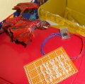
Here an update.
Its now wired up completely. Havent yet tested with the PIC.
2 LEDs in series for each segment.
Maybe it wont be bright enough and will need higher driving voltage.
The 16F54 could be used for kindof a small clock but its not comfortable and not enough to use i2c realtime clock chip.
So I will use another PIC for that, then put all in a small plastic case, with a power supply PCB from a USB charger. Just fits into the battery compartment! Even a US plug so it goes straight into the wall outlet (needs an adapter tough).
Attachments
-
 429.3 KB Views: 83


