74LS90 ic undefined reset pin. unable to count.

dl324

Joined Mar 30, 2015
17,237
I got no luck I measure HIGH on pin 14 "clock" of 72LS90 coming from AND gate. but its not counting. the catch is it counts only when for example I turned it on and the minutes Starts on a number not 0, if for example I started with 5 it will count 6 and so on but will stop counting again ones it hit 0.
The HIGH output from the AND gate should be very brief. When 6 is decoded, the S10 counter should be reset (and the S1 counter if you did as I suggested to reduce the number of OR "gates" required for reset) and the M1 counter should be incremented when the seconds counters are reset.

Are you doing this in a simulator? Or on a breadboard?
 

Thread Starter

gyue

Joined Jun 6, 2024
17
Are you allowed to replace IC3 and IC5 with 74LS92?

That would simplify the circuit.
I cant as that would need major changes in our pcb

The HIGH output from the AND gate should be very brief. When 6 is decoded, the S10 counter should be reset (and the S1 counter if you did as I suggested to reduce the number of OR "gates" required for reset) and the M1 counter should be incremented when the seconds counters are reset.
It should when count because it resets but for some unknown reason it's stubborn to count when starting from 0.

Are you doing this in a simulator? Or on a breadboard?
on a pcb so I can't make any major changes on this project.


It has to do with the 72LS90 decade counter that I could not figure out.
 
Last edited:

dl324

Joined Mar 30, 2015
17,237
clockCropped.jpg
a double sided pcb,
If you're given a PCB that implements the clock, what are you supposed to do? Did you solder anything?
The value on MM here is due to manual input it still doesn't count from 0 to 1.
What is the source of the clock? What do you mean by manual input?
what's a decoupling caps. I searched it but don't know how to implement
Decoupling caps are used on just about all circuits to avoid glitches on the power line, from switching logic in your case.

The conservative rule of thumb is one ceramic decoupling cap (0.001-0.1uF) per power pin and one or more larger electrolytic caps. They should be placed to minimize inductive parasitics.
 
Last edited:

Thread Starter

gyue

Joined Jun 6, 2024
17
w
If you're given a PCB that implements the clock, what are you supposed to do? Did you solder anything?
What is the source of the clock? What do you mean by manual input?
Decoupling caps are used on just about all circuits to avoid glitches on the power line, from switching logic in your case.

The conservative rule of thumb is one ceramic decoupling cap (0.001-0.1uF) per power pin and one or more larger electrolytic caps. They should be placed to minimize inductive parasitics.
we were not given pcb we made it from scratch.

the source of clock is either ac to dc using diode rectifier and a 12v battery. switched using spdt. then run through 9v regulator that goes to timer and common of 7 segments. the IC'S have they're own 5v regulator

I meant by manual input is I connected 5v on pin 14 of MM counter and it still doesn't count

I will try adding decoupling cap.
 
Last edited:

dl324

Joined Mar 30, 2015
17,237
we were not given pcb we made it from scratch.
Are you certain your board doesn't have any mistakes or defects?
a 12v battery. switched using spdt.
Do you have the switch debounced? If you don't, you'll likely have erratic clocking using the switch.
9v regulator that goes to timer and common of 7 segments.
That seems unnecessary to me. The BCD to seven segment decoders can only source so much current and operating the displays from the 5V supply would have eliminated the 9V regulator.
I meant by manual input is I connected 5v on pin 14 of MM counter and it still doesn't count
You need a falling edge to clock the counter.
 
Last edited:

Thread Starter

gyue

Joined Jun 6, 2024
17
Are you certain your board doesn't have any mistakes or defects?
I'm pretty certain I've checked it multiple times theres been no short or wrong lines. The only thing I did which I know wrong is the pull down resistor at the bottom of pcb. I have no considered adding them in the initial design as I was ignorant of it.

Do you have the switch debounced? If you don't, you'll likely have erratic clocking using the switch.
I have researched how to do this but see its complicated needing SR latch and or dedicated device.
or this
1719573198119.png

this is my schematic is it still necesarry?
1719573339064.png

That seems unnecessary to me. The BCD to seven segment decoders can only source so much current and operating the displays from the 5V supply would have eliminated the 9V regulator.
the seven segments display requiring 8v base on data sheet given.

You need a falling edge to clock the counter.
so thats what happens... in my case I just randomly press the resistor i placed on pin 14 and ground to some other pads in the back of my pcb. Which I know is bad but I only learned now from you what a falling edge is and still not fully understand it.

PERHAPS thats also the reason why my counter is not counting even tho its getting a logic high from the AND gate.
 

dl324

Joined Mar 30, 2015
17,237
I'm pretty certain I've checked it multiple times theres been no short or wrong lines. The only thing I did which I know wrong is the pull down resistor at the bottom of pcb. I have no considered adding them in the initial design as I was ignorant of it.
Did you breadboard your circuit to confirm that it worked before committing the design to a PCB?
this is my schematic is it still necesarry?
You seem to be showing a regulator that's switched with no context regarding how it's being used.
the seven segments display requiring 8v base on data sheet given.
That seems like nonsense to me. Post the datasheet.
 
Last edited:

Thread Starter

gyue

Joined Jun 6, 2024
17
Did you breadboard your circuit to confirm that it worked before committing the design to a PCB?
I did not, which is a massive mistake on my end, we were given a month to complete this project. I know plenty of time but still pretty hard considering I'm soloing this project.
the only thing I confirm on breadboard was the 8v for the 7 segments displays. It does not light up unless its 8v as I am using 2.3" displays.

You seem to be showing a regulator that's switched with no context regarding how it's being used.
As for the regulator, here it goes to the 555 timer responsible for 1hrz and a variable pulse which then goes to SS counters.
1719584930870.png
That seems like nonsense to me. Post the datasheet.
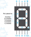
I do not have a data sheet for the 7 segments even when I search the model " sh23101bs" with no luck. All I can provide you is that its a common anode and it works only when voltage is at least 8v or I probably did the breadboard wrong since I tried running it from if I remember correctly 5v reg, it didn't light up. what I have here is only the pins.
1719585498988.png

*also this is now considered a failed project and just wanna be able to learn more about it and my shortcoming for future projects.
 

MrChips

Joined Oct 2, 2009
31,214
C1 and C2 capacitors are in the wrong place. They should be on the input pin of the 3-terminal regulator.
You also need a 1μF capacitor on the output side of the regulator.

Also, you need a 10μF between Vcc and GND of the NE555 timer IC.

(It is a pity that they don't teach about the importance of power supply decoupling capacitors in school.)
 

dl324

Joined Mar 30, 2015
17,237
I did not, which is a massive mistake on my end, we were given a month to complete this project. I know plenty of time but still pretty hard considering I'm soloing this project.
Learn from your mistakes. I only recall making one PCB without prototyping the circuit (because it was so simple, how could anything go wrong?). I never got it to work because I couldn't find a way to prevent a relay from perturbing the rest of the circuit.
the only thing I confirm on breadboard was the 8v for the 7 segments displays. It does not light up unless its 8v as I am using 2.3" displays.
What is the forward voltage of one of the segments?
As for the regulator, here it goes to the 555 timer responsible for 1hrz and a variable pulse.
The regulator symbol needs to be labeled to indicated that it's 5V.

Leaving the control pin on the 555 timer isn't recommended because noise can be coupled to that input.

Whoever designed the circuit simulator you're using must have thought that using curved corners on routes was "cute". I have never seen schematics drawn by professionals do that. We prioritize readability over cute.
 

Thread Starter

gyue

Joined Jun 6, 2024
17
C1 and C2 capacitors are in the wrong place. They should be on the input pin of the 3-terminal regulator.
You also need a 1μF capacitor on the output side of the regulator.
Also, you need a 10μF between Vcc and GND of the NE555 timer IC.

(It is a pity that they don't teach about the importance of power supply decoupling capacitors in school.)
the capacitor is noted. as for the 10uF it would affect the 1hz clock I need, perhaps I can still achieve that but with lower resistor.
also for this project all passive components(resistor, capacitor,etc.) needs to be smd

Learn from your mistakes. I only recall making one PCB without prototyping the circuit (because it was so simple, how could anything go wrong?). I never got it to work because I couldn't find a way to prevent a relay from perturbing the rest of the circuit.
I will.

What is the forward voltage of one of the segments?

The regulator symbol needs to be labeled to indicated that it's 5V.

Leaving the control pin on the 555 timer isn't recommended because noise can be coupled to that input.

Whoever designed the circuit simulator you're using must have thought that using curved corners on routes was "cute". I have never seen schematics drawn by professionals do that. We prioritize readability over cute.
I think that would be 8v I don't know how to check it but it doesn't light up with my digital tester, and with analog it was set to 10x I think and it barely lights up.

as for 555 that is noted, I will connect it with capacitor next time.

as for circuit simulator do you have recommendation that doesn't require a payment. if none what would be the ideal software?
 

dl324

Joined Mar 30, 2015
17,237
I think that would be 8v I don't know how to check it but it doesn't light up with my digital tester, and with analog it was set to 10x I think and it barely lights up.
That isn't a quantitative statement. You can measure the forward voltage using a sufficiently high power supply voltage and a current limiting resistor connected to a segment. That may be problematic if you don't have an extra display.
as for circuit simulator do you have recommendation that doesn't require a payment. if none what would be the ideal software?
The logic simulator I use is called Digital Works. It's free, but doesn't support analog components. It doesn't come with any useful commercial parts. I've spent many hours creating my own custom parts.

1719592597490.png
Note that I observed that the A output is often used to provide the C1 clock, so I arranged the symbols pins accordingly. Since counter chips are usually used in counters, I arranged the pins to facilitate cascading as I've indicated.

Also note that I'm mixing TTL and CMOS parts. Digital Works doesn't care about voltage levels, loading, propagation delays, etc.

It doesn't assign component designators, and I don't care to take the time to add them. If I want a schematic, I'll enter the circuit in a schematic editor. I use an old, free version of Eagle. It has 74LS90, but not 74LS47, and I don't care to take the time to create it. I only recently started adding pin numbers to my symbols in Digital Works.

For the very rare occasions that I want to simulate an analog circuit, I'd use LTspice. But, I'd never use LTspice to simulate a digital circuit. It isn't set up to do that by default and I don't care to take the time to do it.
 
Last edited:

MrChips

Joined Oct 2, 2009
31,214
the capacitor is noted. as for the 10uF it would affect the 1hz clock I need, perhaps I can still achieve that but with lower resistor.
also for this project all passive components(resistor, capacitor,etc.) needs to be smd
Power supply decoupling capacitors go across the power rail. They will not affect the signals.
Use 1μF - 10μF SMD capacitors. Even 4.7μF is better than no capacitor.
 

Thread Starter

gyue

Joined Jun 6, 2024
17
That isn't a quantitative statement. You can measure the forward voltage using a sufficiently high power supply voltage and a current limiting resistor connected to a segment. That may be problematic if you don't have an extra display.
I understand that's my bad, It doesn't run on any voltage under 8v base on regulators I've tried.

The logic simulator I use is called Digital Works. It's free, but doesn't support analog components. It doesn't come with any useful commercial parts. I've spent many hours creating my own custom parts.
I will explore this, tho I see clocks similar to our project use Proteus. I'd believe with the amount of clocks simulated through it that it would be reliable.

Also note that I'm mixing TTL and CMOS parts. Digital Works doesn't care about voltage levels, loading, propagation delays, etc.

It doesn't assign component designators, and I don't care to take the time to add them. If I want a schematic, I'll enter the circuit in a schematic editor. I use an old, free version of Eagle. It has 74LS90, but not 74LS47, and I don't care to take the time to create it. I only recently started adding pin numbers to my symbols in Digital Works.

For the very rare occasions that I want to simulate an analog circuit, I'd use LTspice. But, I'd never use LTspice to simulate a digital circuit. It isn't set up to do that by default and I don't care to take the time to do it.
What's wrong with mixing TTL and CMOS? one youtube video I watched was that its using 4026 as counter to and using 74LS11, 3 input AND gate to implement the clock.

as for the reason I didn't use that was because in my simulator, the 4026 doesn't count if the voltage doesn't reach 5.5V and the output of 74LS11is only 5V.I learned too late that it works and it would have lessen the complexity and expenses of this project. I should have checked the datasheet.

It doesn't assign component designators, and I don't care to take the time to add them. If I want a schematic, I'll enter the circuit in a schematic editor. I use an old, free version of Eagle. It has 74LS90, but not 74LS47, and I don't care to take the time to create it. I only recently started adding pin numbers to my symbols in Digital Works.

For the very rare occasions that I want to simulate an analog circuit, I'd use LTspice. But, I'd never use LTspice to simulate a digital circuit. It isn't set up to do that by default and I don't care to take the time to do it.
I understand, you have been really helpful in the learning process of this project, Thank you.

Power supply decoupling capacitors go across the power rail. They will not affect the signals.
Use 1μF - 10μF SMD capacitors. Even 4.7μF is better than no capacitor.
Will do.
 

dl324

Joined Mar 30, 2015
17,237
I will explore this, tho I see clocks similar to our project use Proteus.
Proteus isn't a free simulator.
What's wrong with mixing TTL and CMOS?
The high level output voltages of TTL aren't guaranteed to be high enough to be recognized as a high on CMOS.

CD4026:
1719599062064.png
74LS11:
LS11specs.jpg
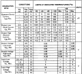
A high output from LS11 is guaranteed to be 2.5V 2.7V, with 3.4 typical (and no maximum specified). High level input voltage for CD4026 is specified as 3.5V minimum. So worst case specification TTL and CMOS parts don't have compatible logic levels.

One way to address this is to put a pull-up resistor on TTL outputs, but that defeats the purpose of having totem pole outputs.

That being said, I have used bipolar 555 timers to clock CMOS logic in hundreds of projects without ever needing a pull-up. Even though the output with a 5V supply is only guaranteed to be 2.75V.

CMOS output voltages are sufficiently high to drive TTL, but the issue is the current that they can source/sink.
one youtube video I watched was that its using 4026 as counter to and using 74LS11, 3 input AND gate to implement the clock.
I've found that a lot of the YT videos are crap. There are several content creators that members praise. One guy is a terrible speaker. Another well-liked (not by me) creator from Australia has a voice that sounds like fingernails scratching a chalkboard to me.

Since these content creators are trying to monetize your time, videos are, almost without exception, far longer than they need to be.
 
Last edited:
Top