74LS90 ic undefined reset pin. unable to count.

Thread Starter

gyue

Joined Jun 6, 2024
17
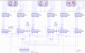
Im in the process of creating a digital clock using 7490 and 7447 in my seconds and minutes the reset pin on all ic's have undefined state(1.3v). making it so even when I put high on ckb it still stays at 0. this error only applies in seconds and minutes my hour counts and resets fine1719142952407.png
 

MrChips

Joined Oct 2, 2009
31,197
does this apply to the 74LS47 too? for the pins 3,4,&5?
Yes. In this case, pins 3, 4, 5 are active low. Hence you need to connect the pins to Vcc.

(Now, somebody is going to claim that their circuit works fine even though they did not connect pins 3, 4, and 5. That is because the input pins of 7400 or 74LS00 series logic IC and similar TTL technology will "float" above the logic high threshold voltage. Don't do this and leave it up to chance. Also note that some beginners get the false impression that an unconnected input is logic 0. This is a mistake.)

If you were using CMOS logic, all input pins, control and data inputs, must be connected to Vcc or GND as appropriate.
Input pins are high impedance inputs. Leaving the pin not connected is the same as a radio antenna which will pick up every AC mains, radio, TV, cell phone and WiFi signal that is nearby.
 

Thread Starter

gyue

Joined Jun 6, 2024
17
I did what you guys mentioned and it works it counts. I run into another trouble the minute counter is not counting due to the AND gate, I checked the pin 4 and 2 and it's giving input high. but the AND gate isn't giving an output HIGH. it's 74LS08 and I've tried swapping it to a different one without changes.

any idea what could be causing this?
 

dl324

Joined Mar 30, 2015
17,221
I did what you guys mentioned and it works it counts.
How about posting an updated schematic that is cleaned up?

Your seconds and minutes counters are essentially the same but, for some reason, you chose to draw them differently.
I run into another trouble the minute counter is not counting due to the AND gate, I checked the pin 4 and 2 and it's giving input high. but the AND gate isn't giving an output HIGH. it's 74LS08 and I've tried swapping it to a different one without changes.
Pin 4 and 2 of what?
 

Thread Starter

gyue

Joined Jun 6, 2024
17
How about posting an updated schematic that is cleaned up?

Your seconds and minutes counters are essentially the same but, for some reason, you chose to draw them differently.
Pin 4 and 2 of what?
the AND gate is getting 5v supply

the pins 2 and 4 of 74LS47 which I connected to the A and B of the AND gate.

I apologize for the schematic.
 

Attachments

Thread Starter

gyue

Joined Jun 6, 2024
17
Unit or 10 counter?
All of the outputs on the minutes decoders have red squares, but they're not displaying 88.
10 counter

as for the commonAnodr 7 segments the red indicators on some of them has hint of darker red indicating LOW voltage while bright red means HIGH
 

dl324

Joined Mar 30, 2015
17,221
10 counter
Your logic is wrong. Explain what you're trying to do.
Was looking at the wrong counters. You should use the output of the AND gate to reset the counter.

Why aren't you having the same problem with the seconds counters?

What are you trying to do with the diodes?
as for the commonAnodr 7 segments the red indicators on some of them has hint of darker red indicating LOW voltage while bright red means HIGH
That's one of the dumber design decisions I've encountered. Proteus uses red for HIGH and blue for LOW. That makes it easy to differentiate levels at a glance. Especially from poorly focused pictures and screen captures.
 
Last edited:

Thread Starter

gyue

Joined Jun 6, 2024
17
Your logic is wrong. Explain what you're trying to do.
Was looking at the wrong counters. You should use the output of the AND gate to reset the counter.

Why aren't you having the same problem with the seconds counters?

What are you trying to do with the diodes?
That's one of the dumber design decisions I've encountered. Proteus uses red for HIGH and blue for LOW. That makes it easy to differentiate levels at a glance. Especially from poorly focused pictures and screen captures.
the seconds connects directly to pulse generator while minutes and hours needs to get the count from AND gate

the RST1 button at bottom next to many Diodes, connects to all reset pins. the diodes next to 74LS90 prevent reset from affecting the circuits it's a make shift way to reset. while the diodes at the bottom is to prevent it affecting other timer from resetting, for example second reaches 60 and resets. I didn't want it to reset the minute and hours.
 

Thread Starter

gyue

Joined Jun 6, 2024
17
hey, are diodes not applicable for fast switching? considering it might be the case why it's not going through the minutes. since the time it take to read pin 2 and 4 is too short and the voltage high not making it to AND gate's input.


if so my entire reset button is making minutes not function.


is there any better way for doing reset?
 

dl324

Joined Mar 30, 2015
17,221
are diodes not applicable for fast switching?
The diode OR gates should be plenty fast for 74LS logic.

is there any better way for doing reset?
But, since you're not using the 2-pin reset capability, you can simplify your logic by tying the two reset pins on each counter together and resetting the unit counters even though you don't need to.

BTW, it was clever of you to notice that since the counters are clocked on the falling edge you didn't need to use an AND gate to decode 9 from the units counters to clock the 10's counters.

Is this really homework? I didn't notice it being in Homework Help yesterday. I almost showed a circuit fragment of how to implement what I described.
 

Thread Starter

gyue

Joined Jun 6, 2024
17
I gave up on reset for the minute and hours timer and will keep it to just seconds. since this project is due today my only issue now is minutes. I opted to using AND gate afterall since I been having issue with not using or so I thought, and minute counter not counting thinking it'll fix it.


as for the AND implementation

I connected the pin 8 and 9 from the seconds timer for binary "0110" in the Input of AND gate. While in the output of AND gate I connected it to the second both reset pins 2&3, and Minutes "ones" pin 14 to act so each time I get binary "0110" I would get High for the minute's counter.

I got no luck I measure HIGH on pin 14 "clock" of 72LS90 coming from AND gate. but its not counting. the catch is it counts only when for example I turned it on and the minutes Starts on a number not 0, if for example I started with 5 it will count 6 and so on but will stop counting again ones it hit 0.

BTW, it was clever of you to notice that since the counters are clocked on the falling edge you didn't need to use an AND gate to decode 9 from the units counters to clock the 10's counters..
hey thank you but I tried changing it thinking it would work this time, I wish I could get the best help on this to find a solution.
 
Top