74HCU04

Thread Starter

Ian0

Joined Aug 7, 2020
13,131
IanO, your graphs are too small to be seen and I could not find them online. Please post the PDF file type.
The absolute maximum allowed output current is 25mA and a load will add to it.
The graphs are probably for a "typical" one and some will produce even more current.
https://assets.nexperia.com/documents/data-sheet/74HCU04.pdf
I don't know why they do all the measurements at 2V 4.5V and 6V. Isn't everyone using it at 5V or 3.3V?
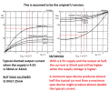
Figure 13 shows a linear amplifier circuit with Vdd=6V

interestingly the same application circuit is in the 74LVCU04 datasheet, but the graphs of Id vs Vi are not included.
 

Bordodynov

Joined May 20, 2015
3,431
And this is how my spice model behaves. I adjusted the dimensions of the transistors so that it would match the datasheet. The transistor models are from NXP.icc.png
 

sparky 1

Joined Nov 3, 2018
1,218
Pierce Oscillator with the 74HCU04 unbuffered hex inverter is said to operate as a linear amplifier. Trimming is Parallel mode not series.
I used the free NI Multisim Live to model of the resonant portion of a Pierce using the AC sweep analysis. It was a copy but the accuracy was
very impressive. I am not sure if the complete detail is really sufficient, the frequency tolerance is extremely accurate for designing very low ppm.
I think noise and parasitic issues require more than average simulation.

Unlike a single mosfet gate the dual gate arrangement is a challenge. Why. In circuit simulation discrete mosfets can help isolate parasitics.
Depending on the application parasitics may not be an issue but waveshape and use of harmonics may be limited.
MOSFET_Paralleling.pdf (mouser.com)

With crystals the circuit values can be found but circuit can be temperamental. An active probe is recommended.
The article explains the challenge of keeping in phase and why the Pierce 74HCU04 oscillator is limited to about 20MHz.
IC CRYSTAL OSCILLATOR CIRCUITS (iqdfrequencyproducts.com)
 
Last edited:

Bordodynov

Joined May 20, 2015
3,431
I do not agree with the conclusions of the article. And I think the reasoning about phases is wrong. But that is up to the author's conscience. And I think the conclusions are not correct, as well as the graph of the limiting resistor.
I did the calculation of the quartz oscillator in LTspice:Crystal20M_AC.pngCrystal20M.png
 

sparky 1

Joined Nov 3, 2018
1,218
The 74HCU04 is not best choice for all applications. The examples noted are some of the cases where it would not be the best choice. The post above has nothing to do with simulation. Since high tolerance crystals are only a subset of applications
I will post resonator with more tolerance allows more pullability. Working with datasheets should not have bearing on simulation.
The drive level can be difficult to measure on the bench without equipment when you substitute a resonator with lower Q.The oscilloscope being helpful in compare startup and rise time shown in the datasheet. The circuits usually work as engineered.

@Bordodynov The conclusion could have been more specific to the narrow subset of crystal pierce oscillators, some have tolerances that are extremely tight. The lab's crystal engineer uses very specialized equipment which is valuable to meet industry's growing requirements. I was not commenting on your work. You do very nice work. Your collection is valuable contribution to those doing simulation.
The LTspice users group used to be a great place to find many useful contributions.

My post regarding design considerations. Those issues may not be transparent in most simulation. (transients and parasitics ) should have been addressed to audio guru, I am sorry about any confusion that I may have caused.

This datasheet reveals setup and implementation of the 74HCU04 with ceramic resonators.
The datasheet also gives implimentation of the 4069UBP with it's charecteristic propagation delay.

https://www.digikey.in/htmldatasheets/production/824525/0/0/1/cstcc2m00g53-r0.html
 
Last edited:
Top