Does anyone have a SPICE model for 74HCU04 in linear mode?
I know it's nothing more than a couple of MOSFETs with the gates and their drain joined together.
Does anyone have a SPICE model for 74HCU04 in linear mode?
I know it's nothing more than a couple of MOSFETs with the gates and their drain joined together.
I think that they simulate 74HC as logic gates (hardly surprising, as they ARE logic gates), but I want to use the HCU04 as a non-linear amplifier.
I remembered a Fairchild application note on the subject, but whilst trying to find it I came across the SPICE model in Theremin World!
I think that they simulate 74HC as logic gates (hardly surprising, as they ARE logic gates), but I want to use the HCU04 as a non-linear amplifier.
I remembered a Fairchild application note on the subject, but whilst trying to find it I came across the SPICE model in Theremin World!
If a 74HCxx IC is biased at half the supply voltage to be a linear amplifier then the current will be massive and the IC will melt.
But it will work perfectly in a simulation that usually allows parts to be badly overloaded.
The Texas Instruments datasheet shows a maximum allowed "transition time" as it heats but I doubt a simulator about knows it.
TS is asking about an HCU part. The quote below is from the family specification datasheet.
Another subset, the XX74HCUXXXXX, consists of
single-stage unbuffered CMOS compatible devices for
application in RC or crystal controlled oscillators and other
types of feedback circuits which operate in the linear
mode.
If a 74HCxx IC is biased at half the supply voltage to be a linear amplifier then the current will be massive and the IC will melt.
But it will work perfectly in a simulation that usually allows parts to be badly overloaded.
The Texas Instruments datasheet shows a maximum allowed "transition time" as it heats but I doubt a simulator about knows it.
Obviously, you have never built one.
I've been building circuits far longer than I've been simulating them. I only learned SPICE during lockdown, thanks mainly to the good people of AAC.
I suggest you read the Fairchild application note which I have now found.
Have you ever seen a Pierce oscillator? Every microcontroller has one, based on a single inverter biassed into linear operation.
Interesting stuff. I'd never thought of using them in radio receivers (but I don't do much radio).
Back in post #8 you used some models of the 74HCU04. I tried the models from the /zzz/logic/74HC directory, which I think are yours, but SPICE just got stuck. Those models have no power supply connections, so are different from the ones in Post #8.
I often use a 74HC1GU04 in a SOT363 package as an amplifier, but I mainly use it on 3.3V. I think Vgs(th) is about 1.5V, so standing current goes up rather fast with supplies over 3.3V.
I made the 74HCU04_my model using proprietary models from NXP. I have dimensioned the transistors so that the datasheet is followed. In addition the chips made by different manufacturers can have different parameters in the amplifier mode. TI technology has higher threshold voltages than NXP. The current consumption of CMOS gates increases when the supply voltage exceeds the sum of the thresholds of the transistors.
Last night Digikey showed they had no stock and it was obsolete for the SN74HCU04 but today they have plenty of them.
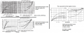
Here is a graph of the typical output current of the weak Cmos CD4069 and MM74C04, the slightly more powerful CD4049 and the much more powerful SN74HC04:
Audioguru again.
The current in the diagrams you show is not the supply current. It is the short-circuit current to the power supply or ground. In amplifier mode, the gates are about half the supply voltage, and in your case 100% of the supply voltage. The currents are significantly different, given the almost quadratic law of the change in current from the gate voltage.
The Cmos curves show the output current into a resistive load at various voltage losses up to 100% voltage loss caused by a shorted load. You can have an output driving an LED without a current limiting resistor and see the amount of current at various supply voltages.
If a Cmos output is linear near half the supply voltage then if both N-channel an P-channel output Mosfets are both turned on the supply current will be massive.
IanO, your graphs are too small to be seen and I could not find them online. Please post the PDF file type.
The absolute maximum allowed output current is 25mA and a load will add to it.
The graphs are probably for a "typical" one and some will produce even more current.
 Facebook
 Google
 GitHub
 Linkedin