 Facebook
 Google
 GitHub
 Linkedin
Hi dear friends,
Thanks for providing the opportunity to interact with you experts!
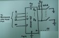
Here I want to perform parallel to serial data conversion. Therefore I am using 74HC165, 8-bit parallel-in/serial-out shift register.
I need C code to read & store the fault status into Variable( say unsigned char). I tried below C code but its not working.
Basically I have an 8 Window Annunciator product where I want to read the Eight different Fault status. These faults can be either Logic 0 or Logic 1. Now these Eight status shall be collected into a Variable(datatype: unsigned char, as value 0b00000000/ 0b11111111 is possible)
Hardware logic is illustrated as shown in fig(A):
D0 to D7 are eight fault status which can be either Logic 0 or Logic 1.
C Code to read & store the status is attached as follows:
So kindly suggest the correct C code to read & store the fault status into Variable.
Thanks!
Regards,
Santosh Bhat
Sr. Engg, Bangalore
Mod edit: code tags
Note that .PDF format is difficult to work with for looking at your code.
Thanks for providing the opportunity to interact with you experts!
Here I want to perform parallel to serial data conversion. Therefore I am using 74HC165, 8-bit parallel-in/serial-out shift register.
I need C code to read & store the fault status into Variable( say unsigned char). I tried below C code but its not working.
Basically I have an 8 Window Annunciator product where I want to read the Eight different Fault status. These faults can be either Logic 0 or Logic 1. Now these Eight status shall be collected into a Variable(datatype: unsigned char, as value 0b00000000/ 0b11111111 is possible)
Hardware logic is illustrated as shown in fig(A):
D0 to D7 are eight fault status which can be either Logic 0 or Logic 1.
C Code to read & store the status is attached as follows:
So kindly suggest the correct C code to read & store the fault status into Variable.
Thanks!
Regards,
Santosh Bhat
Sr. Engg, Bangalore
C:
void CHK_FAULT_INPUT(void)
{
   unsigned char a=0, Val=0;

   PL_ENABLE = 1;
   SERIAL_CLK = 0;
   CHIP_ENABLE = 1;
   PL_ENABLE = 0; // PL
   asm("nop");
   asm("nop");
   CHIP_ENABLE = 0; // CE
   asm("nop");
   asm("nop");
   SERIAL_CLK = 0; // CP
   asm("nop");
   asm("nop");
   SERIAL_CLK = 1;
   asm("nop");
   asm("nop");

// FAULT_PAT: Q7
   if((FAULT_PAT & 0b00000001) == 1)
     FAULT_InP1 = 0b00000001;
   else
     FAULT_InP1 = 0b00000000;

   asm("nop");
   SERIAL_CLK = 0;
   asm("nop");
   asm("nop");
   SERIAL_CLK = 1;
   asm("nop");
   asm("nop");

   if((FAULT_PAT & 0b00000010) == 1)
     FAULT_InP2 = 0b00000010;
   else
     FAULT_InP2 = 0b00000000;

   asm("nop");
   SERIAL_CLK = 0;
   asm("nop");
   asm("nop");
   SERIAL_CLK = 1;
   asm("nop");
   asm("nop");

   if((FAULT_PAT & 0b00000100) == 1)
     FAULT_InP3 = 0b00000100;
   else
     FAULT_InP3 = 0b00000000;

   asm("nop");
   SERIAL_CLK = 0;
   asm("nop");
   asm("nop");
   SERIAL_CLK = 1;
   asm("nop");
   asm("nop");
   if((FAULT_PAT & 0b00001000) == 1)
     FAULT_InP4 = 0b00001000;
   else
     FAULT_InP4 = 0b00000000;

   asm("nop");
   SERIAL_CLK = 0;
   asm("nop");
   asm("nop");
   SERIAL_CLK = 1;
   asm("nop");
   asm("nop");
   if((FAULT_PAT & 0b00010000) == 1)
     FAULT_InP5 = 0b00010000;
   else
     FAULT_InP5 = 0b00000000;

   asm("nop");
   SERIAL_CLK = 0;
   asm("nop");
   asm("nop");
   SERIAL_CLK = 1;
   asm("nop");
   asm("nop");

   if((FAULT_PAT & 0b00100000) == 1)
     FAULT_InP6 = 0b00100000;
   else
     FAULT_InP6 = 0b00000000;

   asm("nop");
   SERIAL_CLK = 0;
   asm("nop");
   asm("nop");
   SERIAL_CLK = 1;
   asm("nop");
   asm("nop");

   if((FAULT_PAT & 0b01000000) == 1)
     FAULT_InP7 = 0b01000000;
   else
     FAULT_InP7 = 0b00000000;

   asm("nop");
   SERIAL_CLK = 0;
   asm("nop");
   asm("nop");
   SERIAL_CLK = 1;
   asm("nop");
   asm("nop");

   if((FAULT_PAT & 0b10000000) == 1)
     FAULT_InP8 = 0b10000000;
   else
     FAULT_InP8 = 0b00000000;

   asm("nop");
   FAULT_InP = FAULT_InP1 + FAULT_InP2 + FAULT_InP3 + FAULT_InP4 +
   FAULT_InP5 + FAULT_InP6 + FAULT_InP7 + FAULT_InP8;
   SERIAL_CLK = 0;
   CHIP_ENABLE = 1;
   PL_ENABLE = 1;
}Note that .PDF format is difficult to work with for looking at your code.
Attachments
-
36.4 KB Views: 19
-
 107.8 KB Views: 23
Last edited by a moderator:


