
74HC series Fanout into AT28C256

Thread Starter

AnalogDigitalDesigner

Joined Jan 22, 2018
121
I have to fanout 15 of the AT28C256 eeproms from one 74HC273 flip flop. I need to know if this will be okay or if 15 will be too much ?

My clock rate will be 4MHz. from what i know the fanout of cmos to cmos is virtually infinite, so this should be fine right?
 

ScottWang

Joined Aug 23, 2012
7,503
The 74HC373 only could provides the current for 11 piece of AT28C256, and that is close to the Imax of 74HC373, so use 2 pieces of 74HC373 is the better choice.

See the page 5 of 74HC273:
Io - output current, -0.5 V < VO < VCC + 0.5 V , Imax = ±25 mA

See the page 5 of AT28C256:
VOL - Output Low Voltage, IOL = 2.1 mA, 0.45 V
VOH - Output High Voltage, IOH = -400 µA, 2.4 V
 

Thread Starter

AnalogDigitalDesigner

Joined Jan 22, 2018
121
But what matters is not the current, because the input gate is a capacitance and it will charge up to 5V in due time. It might just be slower.

Should I split the signal from the 74hc273 and send it into two 74hc244 buffers, and from each buffer into seven AT28C256 ?
 

ScottWang

Joined Aug 23, 2012
7,503
I was too focus on the output side, so it was wrong for the input current of AT28C256 shown on #3, the only issue should be on the input capacitance.

See the page 5 of AT28C256.
Ili - Input Load Current, Vin = 0V to VCC + 1V, 10 µA

See the page 6 of AT28C256.
tACC -- Address to Output Delay, 150nS(AT28C256-15), 200nS(AT28C256-20), 250nS(AT28C256-25), 350 nS(AT28C256-35).

See the page 7 of AT28C256.
f =1Mhz.
Cin -- 4pF(type), 6pF(max), Vin = 0V
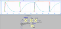
15 pieces of AT28C256 then the Cin_total = 4pF * 15 = 60 pF.

The clock is 4Mhz(250nS) and the Cin is 60pF.

I was used the online calculator to do a little calculation:
RC Filter Cutoff Frequency Calculator.

C = Cin = 60pF.
R = 1Ω, f = 2653927813.2
R = 10Ω, f = 265392781.3
R = 100Ω, f = 26539278.1
R = 200Ω, f = 13269639.1
R = 500Ω, f = 5307855.6
R = 1K, f = 2653927.8

If the frequencyies have any meaning then the Cin should be not a problem, and only needs one 74HC373 that it can be latch the data, the 74HC244 just a buffer.
 

Thread Starter

AnalogDigitalDesigner

Joined Jan 22, 2018
121
I was too focus on the output side, so it was wrong for the input current of AT28C256 shown on #3, the only issue should be on the input capacitance.

See the page 5 of AT28C256.
Ili - Input Load Current, Vin = 0V to VCC + 1V, 10 µA

See the page 6 of AT28C256.
tACC -- Address to Output Delay, 150nS(AT28C256-15), 200nS(AT28C256-20), 250nS(AT28C256-25), 350 nS(AT28C256-35).

See the page 7 of AT28C256.
f =1Mhz.
Cin -- 4pF(type), 6pF(max), Vin = 0V
15 pieces of AT28C256 then the Cin_total = 4pF * 15 = 60 pF.

The clock is 4Mhz(250nS) and the Cin is 60pF.

I was used the online calculator to do a little calculation:
RC Filter Cutoff Frequency Calculator.

C = Cin = 60pF.
R = 1Ω, f = 2653927813.2
R = 10Ω, f = 265392781.3
R = 100Ω, f = 26539278.1
R = 200Ω, f = 13269639.1
R = 500Ω, f = 5307855.6
R = 1K, f = 2653927.8

If the frequencyies have any meaning then the Cin should be not a problem, and only needs one 74HC373 that it can be latch the data, the 74HC244 just a buffer.

Hi Scott,

thank you very much for your help.

So it should be fine right.........because the input current to a AT28C256 is 10uA for it to operate at 150ns delay (AT28C256-15), and a 74HC273 can supply up to 25mA to its outputs.... ? So we should be fine Scott........
 

ScottWang

Joined Aug 23, 2012
7,503
I didn't use 74HC373 much, because I was changed to 74hC574(upgrade the pin out for 74HC374).

You can try it only use one bit or two bits and grounded the other pins for the input of AT89C256, so connect 10~15 pieces of AT89C256 in parallel and to see does the data read or write is ok or not, the /CE pin should be separated by the I/O of uC or decoder.
 

Thread Starter

AnalogDigitalDesigner

Joined Jan 22, 2018
121
I didn't use 74HC373 much, because I was changed to 74hC574(upgrade the pin out for 74HC374).

You can try it only use one bit or two bits and grounded the other pins for the input of AT89C256, so connect 10~15 pieces of AT89C256 in parallel and to see does the data read or write is ok or not, the /CE pin should be separated by the I/O of uC or decoder.
The 574 has an OE pin rather than the CLEAR pin and I really need the CLEAR for this one which 273 has. For registers I like to use 73HC377 because it has a nice INPUT_ENABLE pin.

I did not understand what you wrote in the second paragraph.
 

ScottWang

Joined Aug 23, 2012
7,503
The 574 has an OE pin rather than the CLEAR pin and I really need the CLEAR for this one which 273 has.
The 74HC373 and 74HC374 were designed for different purpose, but in some cases that you still can use 74HC374 to reach to function that 74HC373 can do, like clear function, when you use 74HC374(or 74HC574) then you can send the data "0" to the input and enable /OE and send the clock to CP, in some situations you can exchange the sequence for /OE and CP.

For registers I like to use 73HC377 because it has a nice INPUT_ENABLE pin.
I can't find the datasheet of 73HC377, do you mean 74HC377?

I did not understand what you wrote in the second paragraph.
It means that normally the input will connect 8 bits, but you just want to try it, so you just connect 1 or 2 bits to try, and other pins of input data all connected to Ground.
 

Thread Starter

AnalogDigitalDesigner

Joined Jan 22, 2018
121
What do you mean the 574 can be cleared? Do you mean just sending 0 to the input pins and then sending a clock pulse to write 0 ? Or is that a special sequence that clears it?

Yes it's 74HC377.
 
Top





