Facebook
 Google
 GitHub
 Linkedin
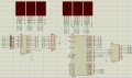
I am trying to interface 74ls145 with 8051 microcontroller to operate 6 seven segment digit multiplexing, any body would like to send me the source code in c language for this purpose please.
7 segment multiplexing
- Thread starter Abdullah Razzaq 1
- Start date