 Facebook
 Google
 GitHub
 Linkedin
Hello,
I have a working 60s counter circuit that I built on a MAX II CPLD (this is the board I'm using: https://www.ebay.com/itm/Altera-MAX...544415?hash=item48576f1a9f:g:5HwAAOSwhzhcDjRn). I have a 1Hz clock signal being generated a 32.768Khz crystal driven by a CD4060, whose divide-by-14 output is fed into a CD4027 to divide-by-2 to generate a 1Hz signal. The 1Hz signal is put through three Schmitt trigger inverters in a 74LS14 to clean the signal up, and then fed into my CPLD. The counter is programmed into the MAX II with six synchronous J-K flip flops whose outputs are also fed to 6 output pins on the CPLD board that drive 6 LEDs.
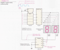
This 60s binary counter works well but I want to display the count on a 2-digit, common cathode 7 segment display (https://www.amazon.com/gp/product/B01BHTI4E6/ref=ppx_yo_dt_b_asin_title_o00_s00?ie=UTF8&psc=1). I don't have the datasheet because I couldn't find it online, but I figured out the pinouts are 1-d, 2-dp, 3-e, 4-c, 5-GND, 6-b, 7-a, 8-f, 9-g, 10-GND. I found this thread yesterday (https://forum.allaboutcircuits.com/threads/how-does-this-circuit-work.102239/) and tried to program that circuit on my CPLD.

I have a 1kHz clock (also generated by the 32.768 kHz crystal) feeding the A1 input on the 74139 and strobing the ENABLE pin (GN on my schematic) on the 74157. The SELECT pin on the MUX is being switched by the output of a J-K flip flop that divides the 1kHz clock frequency in half. The 7449 outputs are connected to 7 pins on my CPLD board that connect to the anodes of the display through 510 Ohm resistors. I've inverted the active-low outputs on the 74139 to drive 2 2N2222 transistors that act as switches for the cathode pins on my display. The base of the transistors are tied to the 74139 outputs through 15k resistors, the emitters are tied to ground, and the collectors are tied to the 7 segment cathodes through 510 Ohm resistors. The transistor switch circuits work, I've tested them with the display separately. I've attached a pdf of what I've programmed to the CPLD. The program compiles just fine and it has been uploaded to the MAX II.
However, the multiplexer circuit doesn't work. When I power on the board (connected via a 5V barrel plug from USB) and connect the pins to their appropriate inputs and outputs on my breadboard (which is powered by a 5V DC supply) only the 60s binary counter works. I think part of the problem is that the multiplexing circuit is supposed to be fed a BCD input, but my counter is binary. However, I don't know how I would convert binary to BCD. Even so, the 7 segment display is not conducting at all, which means something else is the problem. I know the MAX II probably can't supply enough current to drive the display, but the LEDs should at least flash on or something if the multiplexing circuit is wired correctly. So I'm not sure what the problem is. Any help would be appreciated.
-D
I have a working 60s counter circuit that I built on a MAX II CPLD (this is the board I'm using: https://www.ebay.com/itm/Altera-MAX...544415?hash=item48576f1a9f:g:5HwAAOSwhzhcDjRn). I have a 1Hz clock signal being generated a 32.768Khz crystal driven by a CD4060, whose divide-by-14 output is fed into a CD4027 to divide-by-2 to generate a 1Hz signal. The 1Hz signal is put through three Schmitt trigger inverters in a 74LS14 to clean the signal up, and then fed into my CPLD. The counter is programmed into the MAX II with six synchronous J-K flip flops whose outputs are also fed to 6 output pins on the CPLD board that drive 6 LEDs.
This 60s binary counter works well but I want to display the count on a 2-digit, common cathode 7 segment display (https://www.amazon.com/gp/product/B01BHTI4E6/ref=ppx_yo_dt_b_asin_title_o00_s00?ie=UTF8&psc=1). I don't have the datasheet because I couldn't find it online, but I figured out the pinouts are 1-d, 2-dp, 3-e, 4-c, 5-GND, 6-b, 7-a, 8-f, 9-g, 10-GND. I found this thread yesterday (https://forum.allaboutcircuits.com/threads/how-does-this-circuit-work.102239/) and tried to program that circuit on my CPLD.
I have a 1kHz clock (also generated by the 32.768 kHz crystal) feeding the A1 input on the 74139 and strobing the ENABLE pin (GN on my schematic) on the 74157. The SELECT pin on the MUX is being switched by the output of a J-K flip flop that divides the 1kHz clock frequency in half. The 7449 outputs are connected to 7 pins on my CPLD board that connect to the anodes of the display through 510 Ohm resistors. I've inverted the active-low outputs on the 74139 to drive 2 2N2222 transistors that act as switches for the cathode pins on my display. The base of the transistors are tied to the 74139 outputs through 15k resistors, the emitters are tied to ground, and the collectors are tied to the 7 segment cathodes through 510 Ohm resistors. The transistor switch circuits work, I've tested them with the display separately. I've attached a pdf of what I've programmed to the CPLD. The program compiles just fine and it has been uploaded to the MAX II.
However, the multiplexer circuit doesn't work. When I power on the board (connected via a 5V barrel plug from USB) and connect the pins to their appropriate inputs and outputs on my breadboard (which is powered by a 5V DC supply) only the 60s binary counter works. I think part of the problem is that the multiplexing circuit is supposed to be fed a BCD input, but my counter is binary. However, I don't know how I would convert binary to BCD. Even so, the 7 segment display is not conducting at all, which means something else is the problem. I know the MAX II probably can't supply enough current to drive the display, but the LEDs should at least flash on or something if the multiplexing circuit is wired correctly. So I'm not sure what the problem is. Any help would be appreciated.
-D
Attachments
-
 295.7 KB Views: 27
 -
1.8 MB Views: 16


