7 segment display with 7447 led decoder(HELP)

Thread Starter

Marcopolo

Joined Dec 7, 2016
11
IMG_4592.JPG 9F56E582-AC6F-47EA-9077-E1BA4A6B4D9F-1848-00000332C98648B2_tmp.png 99E15877-2A7C-44B2-B590-8D788260A434-1848-0000033302069BBE_tmp.png IMG_4592.JPG 
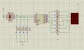
Don't know if I've come to the right place to ask questions but According to the picture provided, what am i doing wrong???! There's no power to the 7 segment display or it just won't light up. Are my writings wrong.? Could it be my resistor values? It didn't seem like I was getting any power to my output pins of the 7447 led decoder. Please help asap. need it to work for a lab grade. Class ends in 1 wk. it would be much appreciated!
 

Marley

Joined Apr 4, 2016
502
I notice that pins 1 to 7 are not connected. Therefore with TTL all these will all be at logic high. Check the logic on the 7447 data sheet. Will any segments light in this state?

Long time since I used a 7447 - must be 40 years or more!
 

MrChips

Joined Oct 2, 2009
30,702
Make sure the 7 segment display is common anode.
Looks like you have a common cathode display.
Connect /LT pin-3 of 7447 to GND for Lamp Test otherwise you will see blank on hex F input.
 

dl324

Joined Mar 30, 2015
16,839
Welcome to AAC!
Don't know if I've come to the right place to ask questions
If this is homework, or school work for which you will receive a grade, it should be in the Homework Help forum. That would indicate that members are to guide you to a solution vs giving you an answer which could result in an accusation of cheating.
but According to the picture provided, what am i doing wrong???!
It would be more helpful if you attached a schematic. Many of us, myself included, are loathe to trace a breadboard for correct wiring.
There's no power to the 7 segment display or it just won't light up. Are my writings wrong.?
You need to tell us whether the display is common anode or common cathode. It seems like you've wired for common cathode.
Could it be my resistor values?
Why are you using different resistor values. From the ones I can see, you're using 470 and 1k ohm. Why?
It didn't seem like I was getting any power to my output pins of the 7447 led decoder.
You have unconnected inputs. What have you been taught about unconnected inputs on TTL?
Please help asap. need it to work for a lab grade. Class ends in 1 wk. it would be much appreciated!
Rate of progress is largely determined by you. Since this is homework, no one should just give you answers.

From the datasheet:
upload_2016-12-7_12-4-43.png
 
Last edited:

WBahn

Joined Mar 31, 2012
29,976
As already noted, a schematic of what you tried to wire up would be extremely helpful.

Also as already noted, how do you expect the 7447 to behave with so many inputs left unconnected? What kind of 7447 is it? TTL, CMOS? The family identifiers are covered up by one of the wires.

You've been asked several pertinent questions and haven't bothered to answer them -- pretty strange behavior for something that you claim is so time-critical.
 

Thread Starter

Marcopolo

Joined Dec 7, 2016
11
I notice that pins 1 to 7 are not connected. Therefore with TTL all these will all be at logic high. Check the logic on the 7447 data sheet. Will any segments light in this state?

Long time since I used a 7447 - must be 40 years or more!
I have connected the 4 pin inputs but wasn't successful because the 7447 driver was receiving power in but wasn't receiving power out pins9-15. That's why I had it disconnected in the picture. I made sure the 7447 was hooked to vcc and ground too.
 

Thread Starter

Marcopolo

Joined Dec 7, 2016
11
Capture.JPG
The 7447 has no inputs. Without them, it makes no outputs. What number do you want the display to show?

ak
My logic is that the display should show a "0" zero regardless of input. But when I send signals to the input pins in binary format, the display should show numbers respectively. however, the display won't even light up as if no power is given.
As already noted, a schematic of what you tried to wire up would be extremely helpful.

Also as already noted, how do you expect the 7447 to behave with so many inputs left unconnected? What kind of 7447 is it? TTL, CMOS? The family identifiers are covered up by one of the wires.

You've been asked several pertinent questions and haven't bothered to answer them -- pretty strange behavior for something that you claim is so time-critical.
 

Thread Starter

Marcopolo

Joined Dec 7, 2016
11
As already noted, a schematic of what you tried to wire up would be extremely helpful.

Also as already noted, how do you expect the 7447 to behave with so many inputs left unconnected? What kind of 7447 is it? TTL, CMOS? The family identifiers are covered up by one of the wires.

You've been asked several pertinent questions and haven't bothered to answer them -- pretty strange behavior for something that you claim is so time-critical.
Sorry may be a bit blurry but my inputs will come from a microcontroller instead of the manual dip switches, this picture i found on google. thats the basic idea im trying to get at from the 7447 to the segment display.
 

Attachments

Thread Starter

Marcopolo

Joined Dec 7, 2016
11
You've been asked several pertinent questions and haven't bothered to answer them -- pretty strange behavior for something that you claim is so time-critical.
I apologize, as I have morning shift work schedule with night classes all throughout the wk. But im back now and will check in again time to time this. I appreciate your time.
 

Thread Starter

Marcopolo

Joined Dec 7, 2016
11
Why are you using different resistor values. From the ones I can see, you're using 470 and 1k ohm. Why?
Yea sorry i know some were of different values as i was short on resistors. I now have changed them to all 320ohm resistors but still to no avail.
 

dl324

Joined Mar 30, 2015
16,839
I now have changed them to all 320ohm resistors but still to no avail.
The resistor values aren't a problem on your breadboard if you can tolerate different segment brightnesses. If you're using a simulator, it might be picky about resistance. MultiSim 14 (actually MultiSimBlue) won't turn on LEDs with 1k ohm and 5V.

Your main problem is that you have the wrong decoder chip. For common anode, you need 7448.
 

MrChips

Joined Oct 2, 2009
30,702
Do me a favor.

Get a DMM with a diode test function.
Set the range switch to DIODE TEST.
Plug in the test leads, RED to +VE input, BLACK to COM input.

Test one of the LED segment, e.g.
RED lead to segment g.
BLACK lead to LED COM.

Reverse the leads, i.e.
RED lead to LED COM,
BLACK lead to segment g.

Under which arrangement does the g segment light up?
 

Thread Starter

Marcopolo

Joined Dec 7, 2016
11
The resistor values aren't a problem on your breadboard if you can tolerate different segment brightnesses. If you're using a simulator, it might be picky about resistance. MultiSim 14 (actually MultiSimBlue) won't turn on LEDs with 1k ohm and 5V.

Your main problem is that you have the wrong decoder chip. For common anode, you need 7448.
I will look into that...thanks
 

Thread Starter

Marcopolo

Joined Dec 7, 2016
11
Do me a favor.

Get a DMM with a diode test function.
Set the range switch to DIODE TEST.
Plug in the test leads, RED to +VE input, BLACK to COM input.

Test one of the LED segment, e.g.
RED lead to segment g.
BLACK lead to LED COM.

Reverse the leads, i.e.
RED lead to LED COM,
BLACK lead to segment g.

Under which arrangement does the g segment light up?
Red Lead to segment g
Black lead to LED COM
 
Top