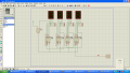
7 segment-BCD

Thread Starter

hariz

Joined Apr 8, 2011
4
hye everyone..senior and junior members..i have 1 problem about 7 segment-BCD,just now i created a logic circuit use ISIS PROTEUS that use to counting total of running items..i success to design a circuit that can count 0 - 8000 BUT the problem is when it reach 8000,the circuit start to counting again from 0 - 8000..i want the circuit just counting once cycle from 0 - 8000 and stop counting..and appear 0000..help me
:confused:..
 

Georacer

Joined Nov 25, 2009
5,182
What Integrated Circuits are you using to implement the counting function? A counter? Flip Flops? A microcontroller?

All these solutions require a different approach. A schematic of your work would be tremendously useful.
 

SgtWookie

Joined Jul 17, 2007
22,230
You are trying to post an image on this website from your computer, but you are the only person that can see it.

You must use the "Go Advanced" and "Manage Attachments" buttons to upload the image to the forum.
 

Thread Starter

hariz

Joined Apr 8, 2011
4
this is my circuit..im happy to hear your advice..pleasant to see your circuit or any url,circuit that i can make reference..thanks
 

Attachments

Georacer

Joined Nov 25, 2009
5,182
Err, a gate schematic or at least an HD screenshot would be useful. With a Photoshop image you limit your benefactors a lot.
 

SgtWookie

Joined Jul 17, 2007
22,230
Your attachment seems to be in Adobe Photoshop format.

Please change it to .PNG format.
1) While you are in Isis Proteus Proteus, capture the screen image of the schematic by pressing Ctrl+PrintScreen
2) Start MS Paint, and paste the image into Paint using Ctrl+V
3) File -> Save As... - then give the file a name, and save it as a .PNG (Portable Network Graphics) file.
 

SgtWookie

Joined Jul 17, 2007
22,230
You are AND-ing U1:B Q3 (high bit) with something; I can't tell if it's +5v power or ground. For the moment, I'll assume that it's a logic high level.

When the count reaches 8000, the output of the AND gate goes high (it might as well not be there, as 1 & 1 = 1) causing the counters to reset to 0; then the output of the AND gate goes low.

Replace the existing AND gate U4 with an inverter.
AND the input clock with the output of the inverter.
 

Georacer

Joined Nov 25, 2009
5,182
The problem with Wookie's suggestion is that it will "freeze" your count to 8000. That's all right if you want it to, but if you want it to go back to 0, then you must implement a sequential circuit in your design.
Keep in mind that Wookie's idea has a race condition hazard. That is, the FF's might reset before the AND gate inhibits the system clock.

I suggest the following changes:

Right after the AND gate, put a D Flip Flop between the AND output and the FF reset pin. That will remove the race condition hazard.
You should also add a fifth Flip Flop to the circuit and a XOR gate to the circuit. Connect the output of the XOR gate to the D Flip Flop. The XOR gate will take its input from the output of the FF and the MSB of the leftmost 7-segment. Take the Q' output of the FF output and AND it with the system clock.
You don't need to reset that FF, unless you want to restart the count.

The system works like so:

  • At first the system counts upwards as usual, without the clock being inhibited.
  • Then when you reach 8000, a HIGH will enter the XOR gate and give a 1 to the FF.
  • When the count resets to 0000, the FF will have an output of 1 by then. That will activate the AND gate and "freeze" the count at 0000. The XOR gate has latched and won't release, unless you reset the fifth FF.
 

Thread Starter

hariz

Joined Apr 8, 2011
4
still can't,maybe device that u mean different that device that i had use,i means devices code ..can i get any references from yours..any URL or gate schematic sir?..pls sir..i have 24hours to present..
 

MrCarlos

Joined Jan 2, 2010
400
Hi hariz

Well, you said in your first message:
“ i want the circuit just counting once cycle from 0 - 8000 and stop counting”

Then once the counter reaches 8000 pulses, stop them coming to U2-B.

Since the Q's outputs of the counters that you are using are true when high (1 Logical)

Use a 2-input OR gate.
The output of this OR gate is connected to pin 15 of U2-B.

An OR gate input is connected to the clock pulses.

The other is connected to pin 9 of U1-B.

So when U1-8 comes to the account 8 (8000), the pulses to U2-B will not get more.

Saludos
a sus ordenes
 

Georacer

Joined Nov 25, 2009
5,182
Hi hariz

Well, you said in your first message:
“ i want the circuit just counting once cycle from 0 - 8000 and stop counting”

Then once the counter reaches 8000 pulses, stop them coming to U2-B.

Since the Q's outputs of the counters that you are using are true when high (1 Logical)

Use a 2-input OR gate.
The output of this OR gate is connected to pin 15 of U2-B.

An OR gate input is connected to the clock pulses.

The other is connected to pin 9 of U1-B.

So when U1-8 comes to the account 8 (8000), the pulses to U2-B will not get more.

Saludos
a sus ordenes
An OR gate won't inhibit the clock pulse from going through.
Remember: 0 OR 1 = 1.

What I had in mind was something like this:


Check if it is working. If not, tell me what's going wrong.

PS. Does anybody know a neat way to modify schematic images like the above?
 

Attachments

Top