 Facebook
 Google
 GitHub
 Linkedin
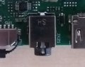
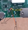
Wonder if anyone can help me identify and get the pin out for a 3.5mm stereo headset socket which is pictured in the photos?
The background is a very elderly relative of mine has a Panasonic TV which (unusually these days) has a 3.5mm stereo headphone socket which, although it is on the back, is still reasonably accessible. She has a set of old Sony wireless headphones and uses these sometimes.
The TV is actually made by Vestel in Turkey and badged up, and they don't have the best reputation for quality/reliability. The stereo socket has eventually failed on two previous PCBs. We are now on the third board - and that really took me some finding on the S/H market and given the TV is nearly 10 years old, I'm not optomistic I'll be able to do that a forth time as and when the current one fails.
Ideally I'd like to move her onto a new TV with Bluetooth and Bluetooth headset but she doesn't cope with technology at all and that is going to be a painful exercise. She's poorly sighted too.
So as a last roll of the dice, I was mulling over whether I could remove the defective socket off one of the previously removed duff boards (which I kept), solder a multicore cable in, and pop a socket in a small project box - making the socket even more accessible AND easy to change if it was to go faulty in use again.
I don't have the right equipment to desolder the socket in one go so I ended up working the pin out as far as I could (accepting that I know this board has a fault on it) and then grinding the socket off with a Dremel as there wasn't space to cut it off, and then desoldering the pins one by one.
I have found 7 pin PCB sockets online but nothing yet with the pin layout I am seeing in this case.
Thanks!
Attachments
-
 392.3 KB Views: 7
 -
 271.3 KB Views: 8
Last edited:


