6v tractor circuit guidance

Thread Starter

robismod

Joined Sep 22, 2015
343
This may be out-of-limits but the folks on this site have always been the best at helping me, so I thought I’d give it a try. ..
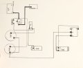
I have an old 1950 International T6 Crawler (dozer) with a 4 cyl. Gas engine. With a 6 volt positive ground system. I reworked the starter on it and found a lot of wiring in bad shape, so I’m about to rewire it. It’s pretty simple and doesn’t have any lights. Has a magneto but previous owner put in an exterior 6v coil, but the magneto still has a wire that comes from a stud on the side. The starter originally had a saddle switch mounted on it, that a pull rod attached to and run through the firewall for Pull to Start. I took it off and changed out the starter stud to a threaded post so I can add a solenoid and Push-To-Start button.
I’ve drawn out a diagram with the help of some folks from a tractor site, but I’m not understanding the “flow” of the circuit. This Positive Ground thing has me scratching my head…I’d like to know how the circuit works when I first pull the Ignition switch to ON and then what happens up until I push the button to start. Many thanks.
 

Attachments

geekoftheweek

Joined Oct 6, 2013
1,429
Luckily the easiest way to understand it is just to switch the '+' and '-' symbols.

I added some arrows and colors to maybe help explain things a bit.
generator-colored.jpeg

The red is your unswitched from the battery to the amp gauge.
The orange is unswitched between the battery and ignition.
The green is switched power out of the ignition.
The purple I assume is between the coil and points.
The light blue would be from your starter button to the solenoid if I understand your updates correctly.
The dark blue shows your charging current flow.

The good thing is if you want to convert it to negative ground the hardest part is going to be repolarizing (?maybe not the best term?) the generator. The starter doesn't care, and you'll just have to swap the coil wires around. https://forums.yesterdaystractors.com/threads/change-positive-ground-to-negative-ground.1184977/

Another thing to consider is a 6V starter will hold up perfectly fine to 12V as long as you don't crank it for extended periods. The generator on the other hand won't survive and the coil won't handle it either. Many people opt for a 10SI Delco (GM) alternator instead of the generator and a 12 volt coil isn't that hard to find. I know I'm getting a bit outside of your question and can completely understand wanting to keep things "original", but converting to a 12V negative ground is pretty simple.
 

geekoftheweek

Joined Oct 6, 2013
1,429
One simple modification I would suggest would be to wire from 'B' on the voltage regulator to the switched side of the ignition. I'll admit I only remember seeing generators and never really understanding them as it was before my time, but I don't think you want constant power to the regulator. Maybe someone a little more familiar will say I'm wrong, but we'll see what happens.

generator-update.jpeg
 

Thread Starter

robismod

Joined Sep 22, 2015
343
Luckily the easiest way to understand it is just to switch the '+' and '-' symbols.

I added some arrows and colors to maybe help explain things a bit.
View attachment 361159

The red is your unswitched from the battery to the amp gauge.
The orange is unswitched between the battery and ignition.
The green is switched power out of the ignition.
The purple I assume is between the coil and points.
The light blue would be from your starter button to the solenoid if I understand your updates correctly.
The dark blue shows your charging current flow.

The good thing is if you want to convert it to negative ground the hardest part is going to be repolarizing (?maybe not the best term?) the generator. The starter doesn't care, and you'll just have to swap the coil wires around. https://forums.yesterdaystractors.com/threads/change-positive-ground-to-negative-ground.1184977/

Another thing to consider is a 6V starter will hold up perfectly fine to 12V as long as you don't crank it for extended periods. The generator on the other hand won't survive and the coil won't handle it either. Many people opt for a 10SI Delco (GM) alternator instead of the generator and a 12 volt coil isn't that hard to find. I know I'm getting a bit outside of your question and can completely understand wanting to keep things "original", but converting to a 12V negative ground is pretty simple.
Thanks so much for that great info. I’ll try and “absorb” it later today when I can focus a little better (hopefully)
 

Thread Starter

robismod

Joined Sep 22, 2015
343
One simple modification I would suggest would be to wire from 'B' on the voltage regulator to the switched side of the ignition. I'll admit I only remember seeing generators and never really understanding them as it was before my time, but I don't think you want constant power to the regulator. Maybe someone a little more familiar will say I'm wrong, but we'll see what happens.

View attachment 361162
Ah…so maybe that area has been the most puzzling to me…so the regulator B tab is “input” power, yes? I know before, I would just pull out on the IGN switch to “turn the system on” and then pull on the starter rod from the firewall to crank and start. Finishing, I’d push IN on the IGN switch and it would die right away. I’m so hung up on how the system works, in order, or the “flow” of it, so I can get a grip on it. On one hand, in its most simple form I’d think it could be this way: battery feed to the IGN switch, pull it to ON and then power goes from it to a simple ON-OFF switch that then feeds the starter. Push that button and she starts. A series flow, so to speak. It’s really that simple, isn’t it? OOPS…I forgot about those other little things, like the coil, mag, regulator, generator…ouch…
 

Thread Starter

robismod

Joined Sep 22, 2015
343
One simple modification I would suggest would be to wire from 'B' on the voltage regulator to the switched side of the ignition. I'll admit I only remember seeing generators and never really understanding them as it was before my time, but I don't think you want constant power to the regulator. Maybe someone a little more familiar will say I'm wrong, but we'll see what happens.

View attachment 361162
Oh and one more thing—that red wire you drew in , does that tap into the minus side of the coil too?
 

geekoftheweek

Joined Oct 6, 2013
1,429
Oh and one more thing—that red wire you drew in , does that tap into the minus side of the coil too?
Yes on that. Typically the generator wire should be a bit heavier gauge than the coil wire so it would be better to go directly to the ignition switch.

I did find a video on how the regulator works and found I may have been mistaken. It appears that the current wiring will work without problems. If you want to take a look https://www.google.com/url?sa=t&sou...3aoNegQIGRAK&usg=AOvVaw2BCGasXZP7iYf85ywmm8HA
does a pretty good describing how it works.
 

geekoftheweek

Joined Oct 6, 2013
1,429
I'll apologize in advance if I'm getting a bit carried away and you understand it up to this point. Your response lead me to believe you may be a bit unsure. The fact you added a solenoid and starter button leads me to believe you have the basics down.

Here is what is happening with the ignition switch turned off. The 'B' terminal of the regulator gets power from the battery at this point, but it is not connected to anything internally at this point.

generator-power-off.jpeg

The green denotes power after the ignition switch is turned on...
generator-power-on.jpeg
The blue denotes pressing the starter button and the starter getting power...
generator-power-start.jpeg
The blue arrows show the engine running and the generator charging. The square wave on the coil '+' is the points opening and closing.
generator-power-running.jpeg
I noticed the regulator wiring didn't quite seem to match what was in the video, but the terminal markings are also different and there's probably more than one way they were built. We used to have a small Cub Cadet that the generator also served as the starter on like an eight or ten horse Kohler in my younger years. It doesn't look like there is any way the regulator in the video would be able to handle that.

I like questions like this as it gives me a chance to actually research and learn something I wouldn't otherwise bother to look in to. Thanks for asking and I hope I was able to help a little.
 

Thread Starter

robismod

Joined Sep 22, 2015
343
I'll apologize in advance if I'm getting a bit carried away and you understand it up to this point. Your response lead me to believe you may be a bit unsure. The fact you added a solenoid and starter button leads me to believe you have the basics down.

Here is what is happening with the ignition switch turned off. The 'B' terminal of the regulator gets power from the battery at this point, but it is not connected to anything internally at this point.

View attachment 361195

The green denotes power after the ignition switch is turned on...
View attachment 361196
The blue denotes pressing the starter button and the starter getting power...
View attachment 361197
The blue arrows show the engine running and the generator charging. The square wave on the coil '+' is the points opening and closing.
View attachment 361202
I noticed the regulator wiring didn't quite seem to match what was in the video, but the terminal markings are also different and there's probably more than one way they were built. We used to have a small Cub Cadet that the generator also served as the starter on like an eight or ten horse Kohler in my younger years. It doesn't look like there is any way the regulator in the video would be able to handle that.

I like questions like this as it gives me a chance to actually research and learn something I wouldn't otherwise bother to look in to. Thanks for asking and I hope I was able to help a little.
No apology needed—I should apologize to you and the others for asking so much.
I so appreciate the effort you and others put forth to help me understand. That was a lot of work but great for me—as I tend to do better with “visual” aids, or trial-and-error attempts. (As long as I’m not blowing something up) Another example of my “need to know”, my wife has been suffering for several months with hands numb and burning, and pain into arms, shoulders, legs. Finally after several tests diagnosis of severe carpal tunnel syndrome. BUT in waiting to hopefully get surgery scheduled, I need to know how and why she had this suddenly happen, and I need to make sense how it can affect shoulder, arm, hips, etc. Something just don’t seem right to me…
 

Thread Starter

robismod

Joined Sep 22, 2015
343
Geekoftheweek
Going deeper here LOL…
When you say that the square wave coming off Coil + is the points opening and closing, (I know that the points are inside the mag area) and there is the one wire connecting to the mag—what is that wire/mag doing?
 

geekoftheweek

Joined Oct 6, 2013
1,429
...there is the one wire connecting to the mag—what is that wire/mag doing?
My apologies for the delay. Between the season's festivities and trying to hammer out some details on my own project I didn't make it back to this.

Long story short that wire is connected to the points which open and close to charge the ignition coil. When the points are closed it grounds that connection (+ in this case) of the coil which causes it to build a magnetic field. The body of the points themselves are grounded to the distributor body creating the ground side of the circuit. When the points open that magnetic field collapses and induces a charge on the secondary coil which is what ultimately creates the spark to make it run.

I have only worked on one old Farmall with a magneto and it's been quite some time. After finding a video to refresh my memory I'm going to assume the magneto coil failed and that is the reason a standard coil was fitted. If it was still using the magneto then that wire would be switched to ground to turn off the engine and left open for the engine to run.
 

Thread Starter

robismod

Joined Sep 22, 2015
343
My apologies for the delay. Between the season's festivities and trying to hammer out some details on my own project I didn't make it back to this.

Long story short that wire is connected to the points which open and close to charge the ignition coil. When the points are closed it grounds that connection (+ in this case) of the coil which causes it to build a magnetic field. The body of the points themselves are grounded to the distributor body creating the ground side of the circuit. When the points open that magnetic field collapses and induces a charge on the secondary coil which is what ultimately creates the spark to make it run.

I have only worked on one old Farmall with a magneto and it's been quite some time. After finding a video to refresh my memory I'm going to assume the magneto coil failed and that is the reason a standard coil was fitted. If it was still using the magneto then that wire would be switched to ground to turn off the engine and left open for the engine to run.
Ahhhhh! Much appreciated. I can follow that.
I’ve been delayed totally lately by the cold and snow, and frankly, my old body just don’t like spending too much time in the cold. So I’ve been using the time to print out your drawings and study them. Yep—I’ve spent a lot of time studying them and the reason for that is I’m constantly questioning my understandings of things, so I end up digging in deeper…kind of like digging down a hole trying to find an opening on the other end! Seems to have become worse in recent years. Then, after I finally master something, if I have to revisit it at a later date, then I have to “relearn” what I’d previously learned! Wife gets amused watching me squirm…she expects it every time I decide to fix something…
 

ronsimpson

Joined Oct 7, 2019
4,646
I had a Ford tractor running 6 Volts. The battery was very pricey compared to a 12V car battery.
I changed out the generator/alternator for a modern one with built in regulator. 12V Removed old regulator.
I think I changed the resistor on the spark coil.
I did not change out the starter. I should have. As long as you don't let the starter run very long it did not get hot.
 
Top