 Facebook
 Google
 GitHub
 Linkedin
Hello,
I'm a novice in this field.
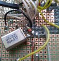
I'm trying to synchronize a 68HC11E1 from homemade circuit, using JBUG11 with an FTDI (USB/UART) interface based on an FT232R.
Limited in equipment (basic multimeter and Arduino UNO R3), I've confirmed that the talker signal emitted by JBUG11 to the RAM is correctly addressed to the PD0/RX pin of the 68HC11 (using the Arduino and RealTerm).
The problem seems come from the clock, which is clocked by an 8MHz crystal with a 10MOhm resistor between XTAL and ETAL and two 23pF capacitors
to ground, according to the manufacturer's specifications.
My measurements are:
XTAL = 2.43V
ETAL = 1.44V
EClock = 2.8mV
RESEToff = 4.97V
RESETon = 0V
MODA = 0V
MODB = 0V
I don't understand what's forbid the Eclock output from emitting its square wave signal and therefore displaying 2.5V on the multimeter.
Does anyone have experience developing an interface for this type?
I'm a novice in this field.
I'm trying to synchronize a 68HC11E1 from homemade circuit, using JBUG11 with an FTDI (USB/UART) interface based on an FT232R.
Limited in equipment (basic multimeter and Arduino UNO R3), I've confirmed that the talker signal emitted by JBUG11 to the RAM is correctly addressed to the PD0/RX pin of the 68HC11 (using the Arduino and RealTerm).
The problem seems come from the clock, which is clocked by an 8MHz crystal with a 10MOhm resistor between XTAL and ETAL and two 23pF capacitors
to ground, according to the manufacturer's specifications.
My measurements are:
XTAL = 2.43V
ETAL = 1.44V
EClock = 2.8mV
RESEToff = 4.97V
RESETon = 0V
MODA = 0V
MODB = 0V
I don't understand what's forbid the Eclock output from emitting its square wave signal and therefore displaying 2.5V on the multimeter.
Does anyone have experience developing an interface for this type?
Attachments
-
 147.5 KB Views: 25
 -
 202.3 KB Views: 27
 -
 241.1 KB Views: 26


