600V DC switch requirement

Thread Starter

ashok.das81

Joined Jan 4, 2017
16
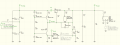
Hi experts. I am making a linear psu capable of O/P 600v @ 300mA. This is for vacuum tube experiments. I need to connect/disconnect the load from the PSU using a switch. I will not turn OFF the PSU itself. I cannot figure out how to switch 600V. My search did not produce any promising results. All I found close is 500V DC circuit breakers that are intended for solar PV application. Those are costly, but I am in doubt how long these will survive at 600V. Please suggest me a solution.
 

LowQCab

Joined Nov 6, 2012
4,022
You should not attempt to switch ~600VDC.
Re-design your Power-Supply so that it provides control of its Output.

High-Voltage Transistors do exist,
but we don't know what you are trying to accomplish,
so it's not possible to make a recommendation.

Since you are using Tubes .......
A large Tube can come pretty close to switching ~600V / ~180W, for certain practical purposes,
but a Tube can't make 600V "safe" for Human-Fingers.

If you would provide detailed information, and preferably a Schematic,
and what the end product is intended to be, you will get more specific help.
.
.
.
.
.
.
 

Thread Starter

ashok.das81

Joined Jan 4, 2017
16
Hi LowQCab. Thanks for your reply. Re designing the power supply that does not produce any undesired O/P during power up is also an option, but the level of testing required with high voltage is currently beyond my reach. So I planned to keep load disconnected during PSU power up and connect the load only after PSU has stabilized. This is kind of similar to PC PSU with a power good signal. In my case I will manually turn on the PSU O/P. Attached here is the schematic of the PSU, its O/P is 275V I need to modify it for 600V. It was designed by Wolfgang GRIEBEL and here is the link.

https://electronicprojectsforfun.wo...pplies/a-275v-50ma-fixed-linear-power-supply/

I am aware that 600 V is not something that should be controlled by just a ordinary toggle switch. Thats why I am looking for a switch or relay that can be used in 600V safely. Currently I am also thinking about IGBT as a switch. 1200V 25A IGBT with 350W power is available and I can make a optically isolated trigger to make that IGBT to turn ON/OFF the 600V output. This is just my thoughts. I need your suggestion.
 

Attachments

MaxHeadRoom

Joined Jul 18, 2013
28,617
There are HV DC relays with magnetic arc blow-out on the contacts, when mechanical switching, some kind of arc elimination is required.
 

LowQCab

Joined Nov 6, 2012
4,022
That's a really crude and dangerous Power-Supply,
it looks like a Voltage-Doubler connected to the Mains.

A custom made 200-Watt Toroidal-Transformer will cost you about ~$100.oo,
and is far safer, very stable, and can provide complete Line Isolation, so that You don't DIE.

Stabilization from zero to full output should take no longer than ~50ms, with zero over-shoot.

The regulation can be very simple, with one high-Voltage-FET and a stack of Zener-Diodes.

To switch the Output, ( if it's really necessary ), You must not only open the connection,
but You must also short the Output to Ground immediately afterwards.

If you want to buy a legitimate Transformer, I'll show You how You can accomplish Your goals.

Line connected Voltage-Doublers are STUPID.
.
.
.
 
If we're talking 300 measly milliamps then we're talking about pilot-duty switch contacts. Look for a relay or switch contact block with NEMA N600, P600 or Q600 contact ratings.

https://en.wikipedia.org/wiki/NEMA_contact_ratings

An Allen Bradley bulletin 800T selector switch fitted with the appropriate contact block might be suited to your needs.

Arc chutes don't come into play until you get into circuit breakers and big load-break power contacts.
 
Last edited:

Thread Starter

ashok.das81

Joined Jan 4, 2017
16
The circuit that I have given here is just how it is simulated. It is not actual. I will definitely use transformer. Toroid is very costly so I am using an ei core transformer. The circuit here shows the main pass transistor and current limiting section and feedback for regulation. It doesn't show the transformer, input line filter, current limiting resistance. I will make a proper diagram and post. For Nema contact rated switch, I am looking for one now.
 

Ian0

Joined Aug 7, 2020
9,667
If you short the terminal called "TPVgate" to ground it will switch off the power supply, although it is not a isolator and it would not be considered "safe" once switched off.
 

LowQCab

Joined Nov 6, 2012
4,022
If we had some details regarding exactly what you are trying to accomplish,
including the nature of the High-Voltage Circuitry you are wanting to test,
you would get much more pertinent answers.
What are you trying to test ????
.
.
.
 

Thread Starter

ashok.das81

Joined Jan 4, 2017
16
Sorry for the silence. I was struck in some health related issues. Now bit recovered but definitely slowed down.
@LowQCab Here is the circuit I plan to test. This is not exactly final but just the preliminary concept. Its a single 807 tube RF amplifier to be used in amateur radio 40m band. I want to test various configuration of this circuit using the psu that I am building. @Ian0 I was thinking about your idea and to make it full-proof I will install two switches or relays right after regulator and before load. Those relays will be disconnected after the regulator mosfet is cutoff, but before doing that I need to understand how the circuit will be stressed if I ground the GATE suddenly and how reliably that can be done. I am still open to all Ideas.
 

Attachments

Last edited:

Thread Starter

ashok.das81

Joined Jan 4, 2017
16
@LowQCab , Thanks for your reply. I have few questions about the circuit you have suggested. Can I use an 1000V mosfet or an 1200V IGBT in this circuit. I have IRFPG50 MOSFET and 25N120 IGBT readily available. IXYS parts are still rare here. Attached are both devices datasheet.
 

Attachments

LowQCab

Joined Nov 6, 2012
4,022
I have no experience with IGBTs, but after looking over the Spec-Sheet,
it looks like it should be OK, but it may dissipate more Heat than the FET.

The FET looks like it should work just fine.

You can also use a Transformer with a smaller VA-Rating,
but pay particular attention to the Isolation-Voltage-Rating,
it needs to be well over 1-KV, higher is better.
The Transformer actually only needs to supply a couple of Amps for a few milliseconds,
then the power requirements revert to just the Quiescent-Current-Level of the Gate-Driver,
which is ridiculously low.
You could probably power this Circuit with 8-D-Cell Alkaline-Batteries for a Year,
depending on how many "On" or "Off" events are added-up.

The LED-Input must get its Power from a separate Low-Voltage Supply,
or even a Single-Alkaline-Cell would do it.
( Remember that it must have a current limiting Resistor, just like any other LED )
Keep the LED-Input-Pins well separated from everything else,
to maintain its 5-KV Isolation-Rating

Also keep in mind that the Copper-Mounting-Surface on the back-side of the FET is at 600-Volts,
so be very meticulous about insulating the FET from its Heat-Sink, and/or,
insulating the Heat-Sink from Fingers or any other metal objects.
.
.
.
 
Last edited:
Check relays made by Kilovac. You do have to watch if they need to switch with no load attached. We used SPdt version for 15kV at 1.5A, but you had to switch with no load. They should be available in the surplus market. They are typicalally vacuum relays.
 

Thread Starter

ashok.das81

Joined Jan 4, 2017
16
@KeepItSimpleStupid I consider Kilovac and similar parts exotic in my country as those are available to commercial buyers only, Even I looked for ABB, TE-Connectivity and OMRAN parts. Those are difficult to obtain for a hobbyist. @LowQCab, Thank you for feedback, I think I have received enough feedback from this forum and all my query have been answered. I really appreciate how AAC empowers the collective technical knowledge. Thank you everyone.
 
Top