Facebook
 Google
 GitHub
 Linkedin
I've been using maxim's DS1822 thermometers successfully for quite a while now. They're very easy to integrate into a 5v circuit, and all they require is a few simple lines of code (assuming you know how to handle timing instructions) to be interfaced to an 8051 MCU.
But today I ran into an interesting mystery. As I've already mentioned, these things work with a 5V supply, and at an average frequency of 16 KHz. They have an open collector i/o that must be pulled up with a resistor to work. See attached datasheet if you're interested in more details.
The way I normally use them is I solder their pins to a #22ga shielded cable, and then I glue them to the part whose temp I want to measure. Then I connect the cable to the MCU's PCB, which is normally no more than 2 or 3 meters away.
Today, I had to use a 6 meter cable and everything went haywire after that. I was getting off the chart readings from them in the lab. And obtained absolutely no readings when I took them out on the field (an industrial environment). At first I thought that I had damaged the wire, but after checking each node with a multi-meter, I couldn't find anything wrong. I didn't check it with a scope, though.
To make the story short, this is what happened. The datasheet recommends that the device be connected this way.

But the data received by the MCU was unintelligible when I used the previous configuration.
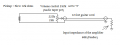
After doing some thinking, tweaking and guessing. I decided to experiment and was finally able to make it work by connecting it this way:

If I remove either of the pull up resistors, the arrangement stops working. My guess is that this has nothing to do with the current that the device is able to sink, and may have lots to do with the cable's length and how its inductance and/or capacitance is affecting the signal. I have a theory about the way both resistors at each end of the cable prevent a capacitive charge from building up. But I'm not sure if I'm saying something stupid here...
Can anyone here explain to me what's going on? I'd like to have a deeper understanding of this sort of phenomena.
But today I ran into an interesting mystery. As I've already mentioned, these things work with a 5V supply, and at an average frequency of 16 KHz. They have an open collector i/o that must be pulled up with a resistor to work. See attached datasheet if you're interested in more details.
The way I normally use them is I solder their pins to a #22ga shielded cable, and then I glue them to the part whose temp I want to measure. Then I connect the cable to the MCU's PCB, which is normally no more than 2 or 3 meters away.
Today, I had to use a 6 meter cable and everything went haywire after that. I was getting off the chart readings from them in the lab. And obtained absolutely no readings when I took them out on the field (an industrial environment). At first I thought that I had damaged the wire, but after checking each node with a multi-meter, I couldn't find anything wrong. I didn't check it with a scope, though.
To make the story short, this is what happened. The datasheet recommends that the device be connected this way.
But the data received by the MCU was unintelligible when I used the previous configuration.
After doing some thinking, tweaking and guessing. I decided to experiment and was finally able to make it work by connecting it this way:
If I remove either of the pull up resistors, the arrangement stops working. My guess is that this has nothing to do with the current that the device is able to sink, and may have lots to do with the cable's length and how its inductance and/or capacitance is affecting the signal. I have a theory about the way both resistors at each end of the cable prevent a capacitive charge from building up. But I'm not sure if I'm saying something stupid here...
Can anyone here explain to me what's going on? I'd like to have a deeper understanding of this sort of phenomena.
Attachments
-
246 KB Views: 8
Last edited: