 Facebook
 Google
 GitHub
 Linkedin
Hello,
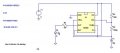
I built the timer circuit using ne555p in the attached file. I am having trouble with my results when I breadboard it. The first pulse is longer than the rest of the pulses. I am assuming this is because the cap is charging from 0V to 2/3V for the first pulse and from 1/3V to 2/3V for all additional pulses. When I measure the second pulse (t1) I get a pulse for 5.2 s and t2(no current out) is 4.4 s. Theoretically, I should get t1=7.6s and t2=6.9s. I tried this circuit with different resistor and capacitor values and have found the same discrepancies between theoretical and experimental results. I thought maybe I fried the chip so I got a new timer and the results are different: t1=8.8s, t2=4.3s. The strange thing is the LED lights up weakly for 2.5s then is brightly lit for 6.4s during the t1 pulses. Also, the current out is 26mA for the first timer and 49.5mA for the second timer. The transient analysis on LTSpice puts the current at 53mA. Anyone have any ideas what the problem is? I believe I have hooked everything up correctly. Its pretty straight forward. BTW, this is a great site. I've been hanging out here for a couple of months and have learned a lot. Thanks.
I built the timer circuit using ne555p in the attached file. I am having trouble with my results when I breadboard it. The first pulse is longer than the rest of the pulses. I am assuming this is because the cap is charging from 0V to 2/3V for the first pulse and from 1/3V to 2/3V for all additional pulses. When I measure the second pulse (t1) I get a pulse for 5.2 s and t2(no current out) is 4.4 s. Theoretically, I should get t1=7.6s and t2=6.9s. I tried this circuit with different resistor and capacitor values and have found the same discrepancies between theoretical and experimental results. I thought maybe I fried the chip so I got a new timer and the results are different: t1=8.8s, t2=4.3s. The strange thing is the LED lights up weakly for 2.5s then is brightly lit for 6.4s during the t1 pulses. Also, the current out is 26mA for the first timer and 49.5mA for the second timer. The transient analysis on LTSpice puts the current at 53mA. Anyone have any ideas what the problem is? I believe I have hooked everything up correctly. Its pretty straight forward. BTW, this is a great site. I've been hanging out here for a couple of months and have learned a lot. Thanks.
Attachments
-
 14.6 KB Views: 37


