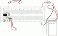
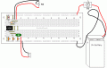
If you look at the 555 hysteretic oscillator link I showed I have a oscillator laid out on a board that is very similar to yours. Do you want me to modify the picture to show the speaker?
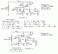
OK, problem one, do you have a schematic you are using? I'm going through the thread, I see more than 3 referenced, but none have been declared as what you are using. I'll draw something up, but I can't tell the values of your components from that small picture. I'll make my best guesses, and can modify my schematic to fit if you get back with me.
Trying to make a project without a schematic is like building a house without plans.
The other circuit depended on a clean output to work, but you are loading it pretty thoroughly with that speaker. This circuit doesn't have that problem.
In both circuits the 555 will get pretty warm, a standard speaker is a hefty load. A piezo will not load the 555 much at all.
Good luck and have fun. I got a new breadboard drawing out of the deal for my PaintCAD package.
Thank you SO much! I really appreciate it! This helps so much! I'm going to go ahead and create design #1, since that's the one you think will be most successful.
So what type of speaker should I use? Does radio shack sell one that'd work that's fairly inexpensive? Also, Would I be able to cut this board in half so I could get two of them out of the 1 board? Thanks!
You will have a problem finding a small speaker that will produce a tone as high as 20kHz. It is called a tweeter and is made for powerful hi-fi systems so it is big and expensive.
Cheap little piezo transducers are made but their frequency response is all over the place with peaks at some frequencies and almost nothing at nearby frequencies. Greeting cards use them and their loudness is very low.
I forgot. I "hear" teenagers playing an MP3 in their earphones fairly far away. The sounds at a distance are only the highest frequencies we can hear.
Try feeding the output of your 555 oscillator to an earphone. I don't know how long it will survive.
How far would the sound travel from an earphone?
also, @Bill
on your schematic it show C2 between the switch and the board, but on your circuit board image it isn't. Do I follow the image, or the schematic?
thanks
It depends on how good your hearing is, and how loud the earphone is.
also, @Bill
on your schematic it show C2 between the switch and the board, but on your circuit board image it isn't. Do I follow the image, or the schematic?
thanks
I'm not Bill, but electrically, C2 is where it should be in both schematics.
The physical layout has to be different from the schematic due to the way the physical parts are made. Schematics are drawn to be as easily understood as possible.
It depends on how good your hearing is, and how loud the earphone is.
I'm not Bill, but electrically, C2 is where it should be in both schematics.
The physical layout has to be different from the schematic due to the way the physical parts are made. Schematics are drawn to be as easily understood as possible.
I'm going with circuit #1
thanks so much.
also, will my cheap greeting card speaker work for now, or do i need to wait till one of the speakers i linked to above comes in the mail? thanks
The very cheap 400W (!) piezo tweeters "reach" to 25kHz. Then maybe with an input of 400W there is a tiny sound? The maufacturer (or buyer) does not show a curve of its response). But your 555 oscillator has an equivalent output of only 0.9W.
Your greeting card speaker might blow up with much more power than it has on a greeting card. But try it.
You can try to tune the frequency of your oscillator so it works at a peak of the cheap piezo thing.

 Facebook
 Google
 GitHub
 Linkedin