555 Timer PWM Hobby Motor Speed Controllor

Thread Starter

Sophiastephanos

Joined Apr 28, 2024
10
Hi all,

Somewhat new to electronics. I studied mechanical engineering and learned a lot of electronic principles in some EE courses but very little hands on application outside of solving drawn circuits.

I am trying to build a speed controller using the following circuit with a CMOS 555 timer for power conservation:

1714939833685.gif
I don’t have a potentiometer so I wired pin 7 directly the node between Ra and Rb. I also don’t have a 10nf cap so I am using a 100nf off of pin 5.

Instead, I tested the model with the following R values:

1)
Ra = 10K
Rb = 10K
C = 50nF

2)
Ra = 10K
Rb = 100K
C = 50nF

3)
Ra = 100k
Rb = 10k
C = 50nF

For some reason all 3 of these setups are resulting in the same RPM/motor voltage drop of 2.5V when providing a 3.3V power supply.

Circuit link:
https://www.electronics-tutorials.ws/blog/pulse-width-modulation.html

Can anyone see a problem with the circuit design/ a reason why changing these values is not changing the motor speed/voltage drop?

My end goal is a specified RPM, so if omitting the pot is my problem, how can I set the circuit up once the R values are defined to omit the pot for a constant specified motor speed?

Thank you!!
Sophia
 

crutschow

Joined Mar 14, 2008
34,918
You need a pot to easily adjust the PWM duty-cycle.

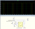
Try this modified circuit configuration (LTspice sim below):
Note, that the frequency doesn't vary for pot settings of 50% (green trace) and 90% (yellow trace) duty cycle.
how can I set the circuit up once the R values are defined to omit the pot for a constant specified motor speed?
Why do you need to remove the pot, as the motor speed will vary depending upon component tolerances, and the load on the motor?
If you need to remove the pot, then measure the pot resistance from each end to the wiper (after removing it from the circuit) and substitute fixed resistors for those two values.

1714943996220.png
 
Last edited:

dl324

Joined Mar 30, 2015
17,227
Welcome to AAC!
I am trying to build a speed controller using the following circuit with a CMOS 555 timer
A CMOS timer can't source much current. With a 1k base resistor, I doubt that a 2N3055 is going to saturate. Do you have any logic level MOSFETs like IRFZ44N?

What is the motor current? You probably need a beefier back EMF diode.
I also don’t have a 10nf cap so I am using a 100nf off of pin 5.
Value isn't very critical.
Instead, I tested the model with the following R values:
Motors/speed control aren't really my thing, but the frequency looks to be an issue to me:
1714944328382.png
 

Thread Starter

Sophiastephanos

Joined Apr 28, 2024
10
Why do you need to remove the pot, as the motor speed will vary depending upon component tolerances, and the load on the motor
I am essentially using this speed controller as a test to define R values so that I can slow the motor down to a specific speed under a specific load.

Thank you for the suggestion! I will try your circuit.
 

Thread Starter

Sophiastephanos

Joined Apr 28, 2024
10
With a 1k base resistor, I doubt that a 2N3055 is going to saturate
This would suggest lowering the base resistor value to fully saturate? I unfortunately am just working with a small kit set right now so I don’t have another option for the transistor atm. What would be the problem with those frequencies?
 

LowQCab

Joined Nov 6, 2012
4,356
I'll bet the next question is going to be .......... How do I reverse the Motor direction ?

Answer .........
Either a DPDT Relay added-on, or
a proper Full-Bridge-Motor-Controller-Chip to replace everything.
.
.
.
 

Thread Starter

Sophiastephanos

Joined Apr 28, 2024
10
How do I reverse the Motor direction
Hahah I can see why you would think that. This is really a simple application, single direction, constant speed rotation. I just need the lowest possible power consumption for a low torque, low RMP application. I am going to further gear the motor speed down but I am currently troubleshooting the ability to change the duty cycle below 50%. I have tried a few difference low duty cycle setups but so far have not achieved the results I am looking for.
 

LowQCab

Joined Nov 6, 2012
4,356
The additional Torque that would be available from Gear-Reduction of some sort,
( Gears, Belt & Pulleys, etc. ),
will tend to render much better stability of the Output-RPM with varying Loads,
if this is important to You.

Simply reducing the Power-Supply-Voltage to the Motor
will usually have very close to the same result as running the PWM% lower,
but there are exceptions to this general-rule.

Using a very low PWM-Frequency will generally tend to give the Motor better "start-up-grunt" Torque,
while not really increasing the RPM as much as would usually be expected.

"Lower-Frequency" is relative to the Inertia of the Motor, ( general weight, and/or, size of the Motor ).
For a small Motor like yours, "Low-Frequency" could be considered to be as high as maybe ~100hz, or lower.

The lowest PWM-Frequency that You would probably find a reasonable use for would be around ~20hz.

This range of Low-Frequency-PWM can be annoyingly NOISY though,
and even cause excessive wear on other associated, and possibly fragile, Components.

Practical High-PWM-Frequency can go all the way to ~20khz, ( and is therefore very quiet ),
or much higher Frequencies, if You don't mind abusing yourself with the
increased complexities that automatically come with employing even higher Frequencies.

Setting a specific PWM%, or Power-Supply-Voltage,
does not guarantee a stable and repeatable, Output-RPM.

How important is it that your Motor maintain an exact RPM with varying Loads ?

How much Inertia and Friction must the Motor overcome in order to get to the desired RPM ?

A Picture would be great, but at least a detailed description is needed.
.
.
.
 
Last edited:

Thread Starter

Sophiastephanos

Joined Apr 28, 2024
10
Let us know how it goes
I received my trim pots in the mail and set up the circuit diagram you provided omitting the LED's, and for some reason with R1 set to 10K, no matter R2, the motor behaves as if it were plugged directly into the power supply. I checked the pots with my multimeter and they are performing as intended. I tested R2 values using a variety of different pot values, and also tried with standard resistors. Am I missing something obvious here? I have tried about 6 different schematics at this point. Could my TLC555CP be the root cause of these repeated failures? I am at a loss. I have tried 5V and 3.3V.
 
Top