 Facebook
 Google
 GitHub
 Linkedin
Hi,
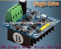
I came across this pre-built H-bridge "IMS-2B" that claims to be able to support up to 200khz. I have attached the specs.
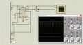
"IN1" and "IN2" pins will be supplied by 555 timer (2 outputs of 100khz square-wave that are inverse to each other).
"V+" pin will be connected to +12V dc supply and "GND" pin will be connected to -12V dc supply.
The 2 output pins of this H-bridge that is supposedly for motor will go to the transmitter coil instead (for wireless power transfer).
just wondering if there will be any problem with this setup ?? Also, the inverted square-wave has lesser amplitude than the other, will this be an issue ?
Thankyou
I came across this pre-built H-bridge "IMS-2B" that claims to be able to support up to 200khz. I have attached the specs.
"IN1" and "IN2" pins will be supplied by 555 timer (2 outputs of 100khz square-wave that are inverse to each other).
"V+" pin will be connected to +12V dc supply and "GND" pin will be connected to -12V dc supply.
The 2 output pins of this H-bridge that is supposedly for motor will go to the transmitter coil instead (for wireless power transfer).
just wondering if there will be any problem with this setup ?? Also, the inverted square-wave has lesser amplitude than the other, will this be an issue ?
Thankyou
Attachments
-
 149.7 KB Views: 19
 -
 182.6 KB Views: 22
 -
 110.3 KB Views: 18
Last edited:


