 Facebook
 Google
 GitHub
 Linkedin
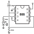
Hello, I have made this delay before on circuit in the past with the 7555 timer (the one that can work from 2 volts) and worked perfectly the first time. Now I made exactly the same thing with regular 555 timer and the led does not turn on unless I touch the output pin 3 with something metal (like multimeter probe) it turns on. Obviously I triple checked the connections on the breadboard like crazy, nothing is loose. I tried a different chip, various values capacitor and resistor combinations. All the same, after the delay led turns very faintly. I use 12V and 820Ω led resistor. Output pin does not go high, only after measuring with the multimeter a few times since I essentially I touch the pin with the metal probe and this somehow triggers it.
Attachments
-
 49.5 KB Views: 29


