555 timer delay and flashing circuit

Thread Starter

Kinsella

Joined Apr 30, 2021
8
Hello everyone, I'm new here so hope this is the correct way to post a question,
I'm working on a project for my local modelling club to create a model version of the lights and sounds that appear when a UK railway crossing barrier is activated.
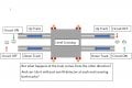
I have a delay circuit using a 555 timer which illuminates a amber LED for 6 seconds then turns it off and activates a second circuit that flashes 2 red leds alternately using another 555 timer circuit. (found both of them on here, including a diagram to connect them, thank you to the helpful person who posted them)
but my dilemma now is i need to add in another delay circuit in front of the first, that turns the entire circuit off after 15 seconds until it is triggered again by a passing train (will be optical sensor with a momentary on switch i think).
can anyone help with how to add a longer delay at the beginning of my circuit please? attached is the circuit I got from this site that I used to create my first delay and the alternate flash circuit.

cheers KevinESP_ 201.png
 

Attachments

Last edited by a moderator:

sghioto

Joined Dec 31, 2017
5,376
Here's my suggestion and I think this is what you are looking for.
IC1 is the 15 second timer activated by the momentary switch connected to pin2. This activates the 6 second timer turning on the amber LED. After it shuts off the red LEDs will start flashing alternately until the IC1 times out.

1620063752802.png
 

eetech00

Joined Jun 8, 2013
3,856
Here's my suggestion and I think this is what you are looking for.
IC1 is the 15 second timer activated by the momentary switch connected to pin2. This activates the 6 second timer turning on the amber LED. After it shuts off the red LEDs will start flashing alternately until the IC1 times out.

View attachment 237378
Hi

When an approaching train is detected:
1. Amber LED should light steady on for 6 seconds
2. Red lights off

After 6 seconds:
3. Amber turns off.
4. Red LEDs begin alternating flash.
5. Red LEDs continue to flash while train is detected.

When train clears the barrier (no longer detected):
6. Red LEDs remain flashing until 15 second timer expires.
7. When 15 second timer expires it turns off the Red LEDs
and also resets the timing circuit.

I believe the above operation is what the TS is looking for.
 

sghioto

Joined Dec 31, 2017
5,376
That makes sense.
My though was the 15 second timer was enough to allow the train to clear the barrier.
Need more info on this momentary switch arrangement the TS has proposed.
 

Thread Starter

Kinsella

Joined Apr 30, 2021
8
Hi everyone, thank you so much for the speedy and helpful suggestions.
at this time i am looking at what is possible or likely in terms of actuation and or deactivation of the sequence.
ideally the lights and siren should sound approx. 3 or 4 secs before the train reaches the barriers (scale speed and timing being a factor here) then the sequence either times out after a predetermined amount of time as in the first suggestion offered or a second activation/monetary or optical switch senses the train and turns it off. I'm meeting with the team from the model club on Wednesday eve (NZ time) so will discuss this further with them, but i do now have a prototype circuit created i can show and demonstrate manually for them thanks to your kind suggestions so we are moving in the right direction.
personally i like the idea of a second actuator when the train reaches a specific point past the crossing, this then allows for slow or fast moving trains accordingly. but happy to accept further suggestions. how for instance would i invoke the second actuator stopping the circuit? would that mean removing the first 15 sec timer circuit?
cheers Kevin
 

Thread Starter

Kinsella

Joined Apr 30, 2021
8
Here's my suggestion and I think this is what you are looking for.
IC1 is the 15 second timer activated by the momentary switch connected to pin2. This activates the 6 second timer turning on the amber LED. After it shuts off the red LEDs will start flashing alternately until the IC1 times out.

View attachment 237378
Thank you I'm working through this circuit at present and it looks great.
 

eetech00

Joined Jun 8, 2013
3,856
Here is a suggestion based on the comments in post #4.
See below.

The timers can be changed as needed (they can also be made adjustable).

The 15 second timer will allow the flashing lights to remain flashing until 15 seconds after the crossing is clear.
The circuit requires an input (shown as a contact labeled "Track") to know the crossing occupancy status.
The "flasher" is held powered off until after the 6 second timer has expired. The flasher is then enabled until disabled by timeout of the 15 second timer.

1620160407146.png
 

click_here

Joined Sep 22, 2020
548
I'd go with the 2 momentary switches rather than timing.

That way the warning is independent of the speed/size of the model train - This allows flexibility and will somewhat future-proof your design. You don't want to be changing R/C values, or reprogramming a microcontroller every time you change the length/speed of your train.

You might want to think about what would happen if you had 2 metres of carriages (like a coal train) and how you'd know that you were at the end - This would require a much longer delay than a train with no carriages.
 

Thread Starter

Kinsella

Joined Apr 30, 2021
8
Hi there, apologies for the delay, work got in the way of this little project. thanks to everyone who replied with suggestions and diagrams. I've now had a chance to present a prototype and discuss with some other club members and we have decided that the circuit should be triggered by a momentary on (probably infrared sensor of some kind, although i need to find a circuit and find one that works) and then deactivated with a similar circuit. the issue now is that the level crossing is a double track crossing, and although trains should only run in one direction on each track, ideally we want to control the on and off at either side of the crossing even if the train runs in the opposite direction. i can see from the helpful suggestions previously that i can trigger momentary on and deactivate by grounding pin 7, so if we look at the on being on the left and off on the right of the crossing, how can i reverse the action without having a second set of detectors>? i also now need to adjust the circuit for 16vdc not 9v which is a pain... any one have nay ideas please? i will upload a diagram of what i mean as soon as i get time cheers Kevin
 

AnalogKid

Joined Aug 1, 2013
10,986
In the schematics of posts #1, #3, and #9, the last 555 oscillator's output can be controlled through its Reset input, removing all power-switching from this stage. This is particularly important for post #3, where the 2nd 555's discharge output is expected to sink both the 555 operating current and the LED current.

ak
 

AnalogKid

Joined Aug 1, 2013
10,986
image attached
As we work through this, it is going to get more complicated. For example:

1. Is the train longer than the distance between the sensors?

2. Can two trains be overlapping at one intersection?

One approach to the logic: assume only one sensor at each end of the intersection, and they both cover both tracks.

a) From the rest condition, either sensor starts the sequence.

b) Once the sequence is started, it is stopped only when both sensors are clear. There is no fixed time for the flashing LEDs. If a train stops in the middle of the crossing for an hour, the LEDs flash for an hour.

ak
 

eetech00

Joined Jun 8, 2013
3,856
image attached
Hi

You can implement this with two detector circuits, one for each track that would detect the train approaching/occupying the crossing. Detection of the train direction isn't required (although there would be in a real highway grade crossing control circuit). Referring to post #9 and assuming the detector output is energized with the crossing un-occupied:

1. The crossing warning would be triggered (or re-triggered) when ANY detector de-energizes.
2. The crossing would begin recovery (15 second timeout) only when ALL detectors are energized.
3. The crossing warning would be re-triggered if the crossing is in recovery mode and ANY detector de-energizes.

In post #9 you can use a 9v regulator to drop the voltage from 16v to 9v or 12v...easy peasy...
 
Last edited:

sghioto

Joined Dec 31, 2017
5,376
any one have any ideas please?
Proposed circuit using IR emitter and receiver diodes. The sensors can be configured as either break beam or reflectance sensors. The schematic shown is using reflectance sensors. Either sensor turns Q1 ON which starts the Flasher. When both sensors are cleared the Latch/Timer circuit keeps power to the Flasher, time dependent on the value of R7. The 470K provides appx 11 seconds using a 12 volt supply (Vcc) before the Flasher resets.
1620696467493.png
 
Last edited:

eetech00

Joined Jun 8, 2013
3,856
Proposed circuit using IR emitter and receiver diodes. The sensors can be configured as either break beam or reflectance sensors. This schematic shown is using reflectance sensors. Either sensor turns Q1 ON which starts the Flasher. When both sensors are cleared the Latch/Timer circuit keeps power to the Flasher, time dependent on the value of R7. The 470K provides appx 11 seconds using a 12 volt supply (Vcc) before the Flasher resets.
View attachment 237966
I think you forgot the timer for the Amber LED(?)
 

sghioto

Joined Dec 31, 2017
5,376
I think you forgot the timer for the Amber LED(?)
I didn't forget about it but don't see the need for it. "Normally" or here in the States when a train is approaching a crossing the Lights start flashing and a bell is dinging. After a few seconds the crossing gates start to lower. So what is the purpose of the amber LED?
Now that I mentioned it why not include the ding ding ding sound and crossing gate mechanism.
 

sghioto

Joined Dec 31, 2017
5,376
Stand corrected, in the UK there is an amber light.
"When a level crossing activates, the yellow light is usually illuminated for 3–5 seconds and then the two red lights flash alternately for the duration of the closure." From Wikipedia.
Revise schematic with 5 second timer for amber LED.
1620704357790.png
 
Last edited:

Thread Starter

Kinsella

Joined Apr 30, 2021
8
Stand corrected, in the UK there is an amber light.
"When a level crossing activates, the yellow light is usually illuminated for 3–5 seconds and then the two red lights flash alternately for the duration of the closure." From Wikipedia.
Revise schematic with 5 second timer for amber LED.
View attachment 237970
That looks very interesting. I like the idea of the two infrared sensors, will either stop the sequence as well as start it? Also you mentioned including the alarm, I've looked at a few but can't get them to work the original circuit and give the correct two tone effect that UK systems have.. so if you have any suggestions on that I would be grateful.
Cheers everyone for help so far this is looking positive now. BTW there is a commercial kit available to do this but cost and freight at the moment to NZ is prohibitive, besides its more fun making it ourselves .
Cheers.
 
Top