 Facebook
 Google
 GitHub
 Linkedin
Hi Folks!
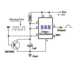
I have undertaken a project which is part of my curriculum and I have chosen to use a 555 timer as a missing pulse detector. I am trying to keep my circuit as simple as possible.
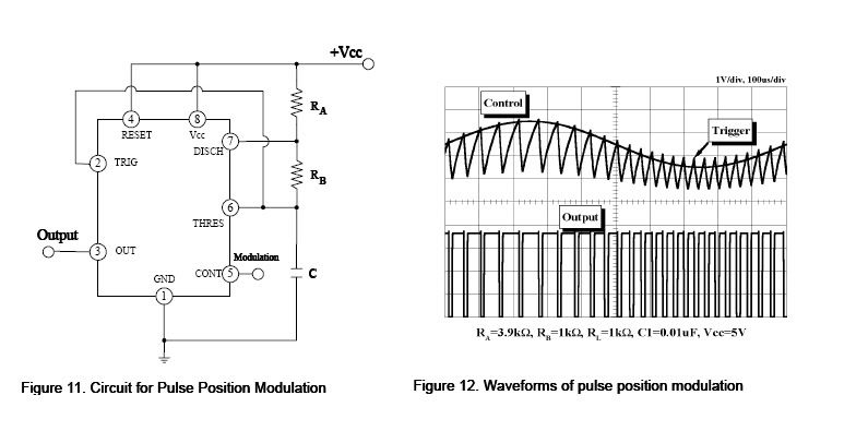
At the outset, the input for the missing pulse detector will be a signal will varying pulse widths. This can be generated using a 555 timer in the astable mode with a modulating signal applied at the Control pin 5. I will get a pulse-width modulated signal at the output pin 3. (This Circuit is functioning well).
I gave this modulated signal as the input to the missing pulse detector circuit operated in the monostable mode. But I am unable to interpret the output waveform of this circuit. I know that this circuit will detect and missing pulse according to its R/C combination i.e. T = 1.1RC.
Any flaws in my circuit design? Any suggestions you can make to improvise?
I have attached the circuit diagrams that I have used.


I have undertaken a project which is part of my curriculum and I have chosen to use a 555 timer as a missing pulse detector. I am trying to keep my circuit as simple as possible.
At the outset, the input for the missing pulse detector will be a signal will varying pulse widths. This can be generated using a 555 timer in the astable mode with a modulating signal applied at the Control pin 5. I will get a pulse-width modulated signal at the output pin 3. (This Circuit is functioning well).
I gave this modulated signal as the input to the missing pulse detector circuit operated in the monostable mode. But I am unable to interpret the output waveform of this circuit. I know that this circuit will detect and missing pulse according to its R/C combination i.e. T = 1.1RC.
Any flaws in my circuit design? Any suggestions you can make to improvise?
I have attached the circuit diagrams that I have used.

")


