Facebook
 Google
 GitHub
 Linkedin
hi
ericgibbs
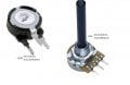
i have tested the resistances of the two potentiometers with results:
thanks have a nice day!
ericgibbs
i have tested the resistances of the two potentiometers with results:
thanks have a nice day!
Attachments
-
 89.5 KB Views: 12
Last edited: