555 monostable mode

Wendy

Joined Mar 24, 2008
23,429
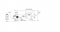
Given the transistor is an amplifier, a 1.3V pulse is plenty.

I've used transistors on 555's to make a retriggerable, the norm for a 555 is non-retriggerable monostable.


The 555 has plenty of drive on pin 3 for many things. Add a transistor to pin 3 (especially a MOSFET) it can go up to amps. If you want a drawing of what I'm talking about just ask.

I'll be straight up, I don't do verbal on circuit, schematics are the language of electronics. I have a fairly deep album that is always growing just because of this.

You can draw your concepts with pencil and paper, or computer. Then take a picture or scan them, it doesn't matter. One schematic is much less likely to be misunderstood.
 

Thread Starter

Etronic

Joined Oct 7, 2011
127
I need the monostable to mimic a SPST tactical momSW on a device i have. When i press this momSW it truns on in 1.5sec.
What i want to do is replace the momSW with a electronic SW
by using the monostable circuit.the output current on the 555 must
mimic that spst SW and the voltage on the output must be low to.
But this circuit may not be retriggerable.

Bill! Sorry for chopping up your circuit. Here what i would like to have happen with that circuit.
I need to trigger the monostable to turn on a device i have,as stated
above.


And yes i would like to see your circuit with the Mosfet on the output of the 555.
Thanks!
 

Attachments

Thread Starter

Etronic

Joined Oct 7, 2011
127
Hi Bill

Can you tell me if this schmatic i made in post 22 will retrigger.
If not what will have to be connected or removed.

Or can anyone tell me if this circuit. will retrigger.

Thanks
 

Wendy

Joined Mar 24, 2008
23,429
We'll start with your schematic...


D1 is not needed, it does nothing for this circuit. The 0.1µF cap between the two 10KΩ resistors will discharge through the resistors. Some advice, put designators on your components, it will make discussing your circuits much easier.

It is basically a standard monostable, it is not a retriggerable type monostable. It will trigger on a rising edge instead of a falling edge, as the transistor circuit is a logic inverter.

I'll draw the MOSFET circuit for you, and will post it on this thread.

You can get more information about drivers in general on my LEDs, 555s, Flashers, and Light Chasers article in chapter 10.

****************************

Turns out I didn't have to draw it, it was already in my notes...


This circuit will need 12V to work correctly, if you use less Vcc voltage you will need a specialized component called a logic level MOSFET. The MOSFET shown is available from Radio Shack. This particular make of MOSFET is among the worst out there (it does work). When on its conductance is very high, most will go well under 1/10 of an ohm. Even so, it is capable of handling several amps comfortably.

If you do need a logic level MOSFET let us know, we'll cross that bridge when we come to it.

Back to the retriggerable type monostable, compare this schematic to yours...


The thing is, the transistor discharges the timing capacitor when it is on. This means the timing does not start until the input of the transistor goes low, or the input opens up.
 

Attachments

Last edited:

Thread Starter

Etronic

Joined Oct 7, 2011
127
Bill

As for the diode in my 555 circuit.Its there so
The diode across the 10K resistor prevents the voltage at pin 2 from rising above the supply voltage when the cap discharges.it's a good idea to limit current when discharging capacitors across switch contacts or transistors.
Reply.
As for the tactile switch in my diagram i like to replace with the monostable 555 circuit,to switch on my device.
Would it be better to have the 555 monostables output pin3 to have a rising or a falling edge on the output to mimic this tactile switch in my diagram. And would i need to use a one shot trigger monosable or would i need a retriggerable monostable 555 circuit.
Reply.

As for your circuit with the mosfet can only work with a dc supply voltage
of 5V-15V.Correct! I would like to use a 1Vto5V logic level mosfet.For my supply voltage. Are there logic mosfets that operate at these small dc supply voltages i can use. And which mosfet would you recommend.Reply.
 

Wendy

Joined Mar 24, 2008
23,429
You will not find that part on any of the 555 datasheets, but if it makes you comfortable. I maintain it is not needed.

There is nothing special about a tactile switch, other than the feel. I bought about a hundred at a discount.

They can vary, but they are already a momentary contact switch for the most part. Think doorbell button.

Is yours different somehow?
 

Thread Starter

Etronic

Joined Oct 7, 2011
127
Bill


The tactile switch i have operates like.When i press the switch to turn on my device for 1.5sec an LED light turn green.Indicating the device is on.
when i release the SW it pop out to it original position. When i turn the device off the SW is push in the LED comes on for 1.5sec then LED shuts off.indicating device is Off.


Do i use a retriggerable 555 monostable or just a trigger monostable. rising or falling edge ouput on pin three.

Which logic level IC could i use. with low supply voltage.
 

radiohead

Joined May 28, 2009
514
Here are some options you can consider:

You can use an NPN transistor with the input signal applied to the base, the collector connected to pin 2 and the emitter to the circuit negative. How much the transistor conducts will depend on the amplitude of the input signal.

Your other choice is using a thyristor (silicon controlled rectifier 2N5062 or equivalent). Connect the anode to pin 2 and the cathode to circuit negative. All that's required to allow the SCR to conduct is a brief pulse to the gate. SCR will stay on, even when the input pulse goes away. The only way to make the SCR turn off is to remove voltage from the anode.
 
Last edited:

Thread Starter

Etronic

Joined Oct 7, 2011
127
Here's an update to my OneShot circuit.


This triggers Low and go's High on the Output of pin3.
It does work. But? Not the way i need it to.

When i put the jumper wire into the Gate of the Mosfet the LED come
on/ But> does not turn off,until i pull the Jp wire out of the gate on the breadboard.

So i put the wire out and then the led times out.or Off.
How can i make the led come on for the 1.5sec duration
with the wire connect to the Gate And have the led go off
After it times out.But it will need to start again with a low trigger
and high ouput.

All help is appreciated.

Any idea How to do this.
 

Attachments

tracecom

Joined Apr 16, 2010
3,944
I haven't read all the posts in this thread, so I don't really know all that you are trying to accomplish. If you want the MOSFET to be controlled by the 555, you will have to connect the output of the 555 to the gate of the MOSFET.
 

Thread Starter

Etronic

Joined Oct 7, 2011
127
Tracecom

No.I don't want the 555 time output to control the mosfet.On the output of timer.

I want the mosfet to trigger pin2 on the 555.So the out go's high.then times out after 1.5sec.

But? When the output is high the LED is on and does not go out.Off.

Read over post 30# Tracecom.
 

Thread Starter

Etronic

Joined Oct 7, 2011
127
I'm thinging i need a conditioner circuit. That's why the Led in my circuit
in post #30 will not time out.Go off?

I assumed you only needed a conditioner circuit is when you connect
a mechanical spst on/off switch.Or a push button momentary switch.

Can some explain this.
 

elec_mech

Joined Nov 12, 2008
1,500
Hi Etronic,

I'm thinging i need a conditioner circuit. That's why the Led in my circuit
in post #30 will not time out.Go off?
First, re-read Bill's response in Post #8: http://forum.allaboutcircuits.com/showpost.php?p=486466&postcount=8

Also take a look at Tracecom's link, specifically the section entitled edge-triggering: http://www.kpsec.freeuk.com/555timer.htm#monostable

In you're latest circuit, it sounds like you're pulling pin 2 low beyond your time duration of 1.5 seconds. If pin 2 is low beyond your time duration, the output will remain high until pin 2 is high again.

I suspect if you simply touched the + lead of your 1.5V to the gate of the MOSFET for less than 1.5 seconds, you'd be set.

Now, if you can't do this and need to leave the 1.5V connected to the gate, then add the triggering circuit (2x 10kΩ and a 0.1uF) like you used in post 22: http://forum.allaboutcircuits.com/showpost.php?p=490131&postcount=22

This is also mentioned in Tracecom's link above under edge-triggering.

I assumed you only needed a conditioner circuit is when you connect
a mechanical spst on/off switch.Or a push button momentary switch.

Can some explain this.
A conditioner circuit is a bit of broad topic. It depends on what you're trying to do. As an example, for an input to a logic circuit, you want a debounce circuit for mechanical switches so mechanical bounce by a single button press isn't mistaken for multiple signals. In the case of your circuit, you want edge-triggering whether you're using a mechanical switch or input signal that is constantly "on" such as a battery input.

The edge-triggering is working two-fold for mechanical switches - it is acting as a sort of debounce AND is preventing the 555 from staying on if the switch is held in the ON position for too long. Since you're hooking up a battery as the input and presumably leaving it connected or at least leaving it connected beyond the time duration of the 555, then the edge-triggering circuit should solve your problem.
 
I suspect if you simply touched the + lead of your 1.5V to the gate of the MOSFET for less than 1.5 seconds, you'd be set.

Now, if you can't do this and need to leave the 1.5V connected to the gate, then add the triggering circuit (2x 10kΩ and a 0.1uF) like you used in post 22: http://forum.allaboutcircuits.com/showpost.php?p=490131&postcount=22


Hi
elec_mech

Thanks for your imput on this.
OK. You are partially right! On what im try to do.I don't want to touch the 1.5V to the mosfet gate for 1.5secs.But? I do know if you touch the gate on the mosfet for
less the a second and pull the wire out the output of the timer and LED times out
and shuts off the led. I do know this because i try it many times.

It is the second part of your ''Reply'' that i need to do.

I need to put a 1.5V to the gate and leave the wire always connected to the mosfet. Because iam using the mosfet as a switch. Which the mosfet triggers pin 2 on the 555 timer the trigger go low so the output go high turns on LED,that stays on
for 1.5sec then times out after the duration and the led turns Off.
Know you're thinking how do i retrigger once the timer times out and the LED go's off.
that come from a 5 day timer that will control the Mosfet went it ready to turn on the mosfet switch to trigger pin 2 on the timer and starts the process all over again.
So the second part of your ''Reply'' is correct!

But i didn't know i ''still'' need to use that conditioner trigger circuit with out the mechainal swithes. Like i did use before.
Now i need to trigger pin2 on its falling edge low to get an high output for ''1.5secs''.
And then when pin two go's high again the output on pin three go's LOW.This is what
i need.

I didn't know how to Quote part of your Post> So i copied and paste it in this post. How do you quote a partial of somebodies Post as you did. elec_mech.
 
Last edited:

tracecom

Joined Apr 16, 2010
3,944
I am no expert, and I am not at my home, so I don't have access to my reference data and may be wrong. But I think that you will need two 555 circuits: one to output a pulse when the MOSFET changes state, and the second to give you the delay you want.
 

elec_mech

Joined Nov 12, 2008
1,500
To quote something, copy the text you want. At the top of the message window is a tool bar. Put the mouse pointer over the icon that looks like a text balloon (like you see in comics). When the mouse is over the right one, it will show "WRAP
tags around selected text". Click on this icon once and paste the text.

Alternately, copy and paste the text you want to quote and type "QUOTE" at the beginning of the quote and "/QUOTE" at the end of the quote. Replace the " with [ and ].

So how long is the timer ON? You just want to make sure your circuit will reset. Do this by adding the conditioner circuit (two 10kΩ resisitors and one 0.1uF capacitor) then connect the 1.5V battery to the MOSFET gate for one minute. Make sure the LED comes on for 1.5 seconds and then turns off and stays off. After one minute, disconnect the 1.5V from the MOSFET gate for a second or two and reconnect. Does the LED come on for 1.5 seconds again? If not, we may need to make this a resettable circuit as Bill suggested.

Tracecom, I think the OP is okay with one 555, but we'll see once the new circuit is tested.
 

Thread Starter

Etronic

Joined Oct 7, 2011
127
elec_mech

So how long is the timer ON? You just want to make sure your circuit will reset. Do this by adding the conditioner circuit (two 10kΩ resisitors and one 0.1uF capacitor) then connect the 1.5V battery to the MOSFET gate for one minute. Make sure the LED comes on for 1.5 seconds and then turns off and stays off. After one minute, disconnect the 1.5V from the MOSFET gate for a second or two and reconnect. Does the LED come on for 1.5 seconds again? If not, we may need to make this a resettable circuit as Bill suggested.
I got the circuit to work like i want it to. And as elec_mech stated.

The LED comes on when i trigger pin2 and stays on for the 1.5s duration as i wanted it to do.Then shuts off for the next trigger of pin2.

But? When i put the battery in its holder to power the circuit the LED comes on, then shuts off.Is there any stray capacitance in the circuit that causes the LED to light before pin2 is triggered.How could i stop the LED from lighting
when i power the circuit up.
 

fila

Joined Feb 14, 2011
64
I am using 555 monostable in my project. When I power on the circuit the 555 always gets triggered. I think that happens because for that brief period of time the battery voltage acts like an impulse which triggers the 555.

On the other hand 555 will also get triggered when the TRIGGER line voltage is below 1/3 * Vcc. So when you start up the circuit TRIGGER line voltage will rise from 0 V to Vcc. You can see that during some brief period voltage is below 1/3 * Vcc and thus the 555 must be triggered. I hope someone can verify this.

Connect the reset pin to ground and then start the circuit. Then tell me what happened.
 
Last edited:

elec_mech

Joined Nov 12, 2008
1,500
But? When i put the battery in its holder to power the circuit the LED comes on, then shuts off.Is there any stray capacitance in the circuit that causes the LED to light before pin2 is triggered.How could i stop the LED from lighting when i power the circuit up.
Let's clarify a bit, which battery are you talking about, the 1.5V battery connected to the MOSFET or the 3V battery connected to the 555?

Assuming the latter, I believe you can solve the problem by adding a power-on reset feature. Take a look here: http://www.kpsec.freeuk.com/555timer.htm#monostable and look at Power-on Reset or Trigger. And I apologize, I read Tracecom's replies but didn't realize this link came from tomega3 originally.

Disconnect pin 4 from 3VDC and put a 10kΩ between pin 4 and 3VDC. Add a 0.1uF ceramic capacitor between pin 4 and GND. When you apply the 3VDC to the circuit, the reset pin will be pulled low momentarily because the capacitor will act as a short to ground until it charges up (within a second or so if that). During this brief period, the 555 will be in reset mode which will keep the output off.

Let us know if this works out.
 
Top