The following are the difficulties I have faced during the above circuit implementation,
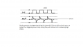
1. 1ms pulse by pressing the trigger micro switch is hard to achieve as it depends on the duration of pressing the switch and is beyond 1ms (depends on the operating person)
2. To overcome the above difficulty I have designed one 3ms 555 astable and is fed to monoshot through Differentiator
3. In the 2nd case I cannot control the count of mono pulses at output as I only want a SINGLE 1ms pulse at 555 mono out.
The following are the difficulties I have faced during the above circuit implementation,
1. 1ms pulse by pressing the trigger micro switch is hard to achieve as it depends on the duration of pressing the switch and is beyond 1ms (depends on the operating person)
2. To overcome the above difficulty I have designed one 3ms 555 astable and is fed to monoshot through Differentiator
This problem is explained in all datasheets for a 555. The datasheet of the NE555 from Philips shows how to fix the problem by AC-coupling the trigger signal (a differentiator).
3. In the 2nd case I cannot control the count of mono pulses at output as I only want a SINGLE 1ms pulse at 555 mono out.
OK, but a monoshot triggered by astable should be able to produce a series of mono pulses (more than ONE) as per the arrival of periodic triggering signals. For my application I only want one 1ms pulse at output.
You don't need an astable to send pulses to the monostable. All you need is the addtion of a resistor and a capacitor to the input of the monostable. It's called a pulse conditioning circuit and it is explained on this web site. Once you add that conditioner to the input pulse, your monostable will produce the length of output pulse dictated by the RC combination you are using, despite how long the input pulse lasts.
Diode prevents the mistriggering during the interval just below 1/3Vcc and above ground level of triggering pulse. Only allow negative spikes to enter the 2nd pin of 555 by bypassing +ve spikes.
I got a PM from the OP, so I am behind this curve.
The problem can be broken down into steps, my article 555 Monostable explain why the input conditioner is required. Other than that the other problem you mention is voltage level, this is explained in earlier articles. You need to understand the drive on something like the 555.
Instead of thinking of the load, go the rest of the way and figure out the currents, it will determine what the output driver will need to look like. I was about to head out the door, but I will get back to this.
Instead of giving a variable voltage for the power supply, pin it down. Worst case (which in this case is the highest voltage) is where you want to go. Is that +12VDC?
1. Other than that the other problem you mention is voltage level, this is explained in earlier articles. You need to understand the drive on something like the 555.
2. Instead of thinking of the load, go the rest of the way and figure out the currents, it will determine what the output driver will need to look like.
3. Instead of giving a variable voltage for the power supply, pin it down. Worst case (which in this case is the highest voltage) is where you want to go.
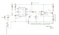
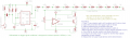
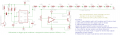
Thanks Bill for your interest, {pls find the attachment and go through the texts in the schematic to know about my requirement}
1. Normally the Differentiator is designed for a periodic pulse input with specific period T.
But in the above application scenario the differentiator is being fed by a single pulse through push switch. So there is no specific T as of one time triggering by pushing the microswitch.
Thus to design Differentiator elements it is assumed to operate the differentiator with pulses of period 625ms>>1ms as we want 1ms pulse out of 555.
2. I would like to get exactly the following volts {three decimal points accuracy} across the transistor emitter load during 11 positions of the selector switch for three loads( 33/68/100-one at a time) without any loading effects.
[0.000V,0.500V,1.000V,1.500V,2.000V,2.500V,3.000V,3 .500V.4.000V,4.500V,5.000V] {irrespective of component tolerances and temperature effects }
3. Supply volt determines the output voltage of 555 at pin 3. So, I will set the supply for the value output of exact 5.000V at 555 output.
NOTE: Can you suggest any other schematic to get 1ms single pulse output with 0 to 5V in 0.5V increments for 33/68/100 Ohm loads one at a time without any loading issues and having less effects of temperature and tolerance of components i.e, linearity error less than 1%
You are missing an important point, the duration of the pulse is independent of the output of the 555, if you want 1ms then you design a simple timer and you are done with it. The load only matters for the current the 555 or driver after the 555, if it can not handle the current then it will blow out.
You pick worst case, the highest current, then design around that.
Like I said, break it down. 1ms is not extremely fast, but many op amps will have problems keeping up with that short duration.
Step 1, design the 555 circuit that does the pulse duration you want and triggers the way you one.
I'll cover step 2 when step 1 is taken care of. Since want precision voltages afterward you will need a higher power supply voltage than the max voltage you want, to provide overhead for the driver. You need to decide this power supply voltage now, and it should be at least 2-3VDC greater than the output voltage range. The exact load simply is not that important, except to make sure you do not exceed the current requirements of the driver.

 Facebook
 Google
 GitHub
 Linkedin