The duty cycle is the ratio of the two resistors since both resistors charge the timing capacitor and only one of the resistors discharges the capacitor.
It cannot reach 50:50 or more unless two diodes are added then a pot can make any duty cycle you want.
Actually, from the conventional astable multivibrator configuration of R1 from Vcc to pin 7, R2 from pin 7 to pins 2&6, and C1 from pins 2&6 to GND, R2 can be replaced with a pot, and a single diode can be used (preferably a Schottky with a low Vf), anode to the wiper, cathode to pin 7, so that the timing cap C1's charge/discharge paths are dependent on the wiper position, thus allowing a wide PWM duty cycle adjustment.
You won't get to 0% or 100% duty cycle, but a range of ~3% to ~97% is do-able.
The duty cycle is the ratio of the two resistors since both resistors charge the timing capacitor and only one of the resistors discharges the capacitor.
It cannot reach 50:50 or more unless two diodes are added then a pot can make any duty cycle you want.
Of course it is different, it has an adjustable duty-cycle.
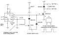
The output can be from pin 7 with a pullup resistor (as I showed before) or from pin 3 like this:
Hi, this is my ckt. i want to know how to connect active gate output common as one method is to place diode at each gate output, but it will be very difficult and costl.
Pls. suggest me how to overcome this..!!
 Facebook
 Google
 GitHub
 Linkedin