That's the kind of problem that I was having when I was last working on my class d amp.
I was able to simulate it by using an opamp with a fairly large value resistor in series with the output around 50 ohms or so. Basically, the integrator capacitor was charge pumping.
FYI I was using a 30MHz video opamp for the square/schmitt but had to use a TL071 for the integrator as the video opamp was *too fast*! It overshot & gave very lumpy outputs especially as its output impedance was even worse than the TL071 and very lopsided in terms of sink/source impedance. Hope that helps, I'll be revisiting my class d stuff soon I hope.
Edit: I was only trying to produce a 650kHz tri wave for switching, but that is not a bad sine wave so I'll keep an eye on this for my future UPS project...
Bill, make the integrator current lower (bigger R, smaller C) to minimize the tits. The crossover distortion in inherent to the LM324, and can be reduced by adding a pulldown resistor from the output to -V. The app notes in the datasheet mention this.
A better solution to both problems is to use a better op amp.
But the lousy old LM324 antique quad opamp is available at RadioShack with some other old antiques.
Maybe a better more modern supplier should be used.
RadioShack got kicked out of Canada. Guess why?
I'll try a better op amp, and increase the resistor values. I'll probably try adding the pull down resistors.
This project will split two ways, one for the ACC book, where Radio Shack parts are the norm. There I will try very specific frequency ranges and whatever else I need to get it to work. I may abandon the 555. Above all, it needs to be as simple as I can make it.
The other project is a instrumentation function generator, something a hobbiest can use. I'll see what op amps are at Tanner's tomorrow, one of my local providers (and they have a nice stock in everything electronic).
The negatives are pretty obvious on the scope, the pluses are the symmetry on the triangle wave was pretty good. I"m not sure about the square wave, the oscilloscope is pretty old, and the specs are pretty down there. I'd like to find a manual for the HP120 sometime, but no luck yet. Still, not bad for $10. All tubes, of course.
Something else to try, use a 7555.
I love the slope on the square wave output. Not a very good slew rate going there.
Interesting note, I swapped out the LEDs with white units, which have a much larger Vf. This would reduce the shoot through a bit, and saw the following changes. It may be I need to redesign the invertor/buffer from scratch. Any ideas?
Before:
After:
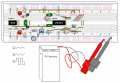
Sorry about the picture quality. I think there is enough detail to see what I'm talking about though.
*******************
After a nights sleep, I remembered what Ron suggested about the collector resistors. Add that to the list of things to try.
Bill, the "tits" on the triangle are caused by the op amp being too slow, and/or not having a low enough open-loop output impedance to absorb the current transients that flow through the integrator R-C network. Another way of looking at is that the harmonics of the fast rise and fall times of the square wave are outside the bandwidth of the op amp. If you want to think of it as shoot-thru, it's through the integrator RC.
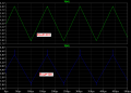
Below is a simulation with behavioral op amps, with the open loop output resistance of the integrator stepped from 1mΩ to 100Ω.
You will notice that the "tits" get much worse as Rout is increased. You should also be able to deduce that, if you make the integrator resistor larger, the amplitude of the tits will decrease.
I also ran sims with higher GBW and higher slew rate on the op amp, and they both helped.
I can't explain it, but the tits did get a lot better with the reduced shoot through. On the slow triangle wave the amplitude was reduced, and even on the fast triangle wave they were a lot narrower.
I'm back from Tanners, with two new op amp types. The MC3403 is supposed to be equivalent to a LM324 except for a much improved cross over. I think everyone knows the TL074 already.
One of the long term goals is to get the intigrator RC values out of the loop. If this does become an instrumentation type of equipment they RC values will be all over the map.
Stray capacitance will cause a lot of that spikyness, if you are still using the plugin breadboard they suck for capacitance?? Like someone suggested you can add a little series resistance to help reduce those spikes too. More R less C.
One of the long term goals is to get the intigrator RC values out of the loop. If this does become an instrumentation type of equipment they RC values will be all over the map.
How can you do that, unless you generate your ramps digitally with a D/A (direct digital synthesis?), or make the whole analog loop a PLL, locked to an external, digitally generated reference?
The integrator time constant is fundamental to the frequency of oscillation.
Range switches for caps, variable resistors for specific frequency? I think you misunderstood what I meant, there will be such a wide range of RC values adjusting them to eliminate a specific problem isn't really a solution, since almost every combination of RC will be used. There will be a max frequency, determined by the op amps most likely. What I have right now most definately is not usable as such, but there is a chance it could be.
If I didn't have a good square wave (if slowed down the slopes, as you commented on) then the tits wouldn't be a problem. Using an op amp to make the square wave (or feed the integrator) definately brings the square wave to speed the following op amp can keep up with. I may yet make a Schmitt Trigger for the ACC book version, but there are lots of things to try first.
I'd say I'm weird, but here I stand in the midst of my fellow techies. This is my idea of fun, and I'm actually learning some hands on too.
OK, now I understand what you meant. Don't you think a decade+ of variable resistance, and decade cap switching, will get you what you want? With a good op amp, a reasonable resistance range is 100k-1Meg.
Actually at higher frequencies, the propagation delays of the Schmitt trigger and the push-pull collector stage can wreak havoc with the frequency vs RC relationship at the higher ranges.
The MC3403 quad opamp is slow (power bandwidth to only 9kHz) almost as bad as an LM324. They call it a quad 741 opamp but with a 3V minimum supply voltage.
Why not use the MC34074 quad opamp with a power bandwidth to 160kHz? Its minimum supply is also 3V.
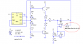
The 555 is a simple 555 Schmitt Trigger. The transistors Q1/Q2 are both an invertor and driver, they take the 555 rail to rail (which a native 555 can not do by itself). The basic circuit needs a noninverting Schmitt Trigger, but I think the 555 is a good design, very predictiable and stable overall.
By adding a integrator to the 555 Hysteretic Oscillator the sawtooth wave has been turned into a precision triangle waveform. The op amps are not fast enough to keep up with the square wave, which is where I'm currently at.
The diodes shape the triangle wave into an approximation of a sine wave (but not perfect, far from it). The buffer after that, the one after the rotary switch, equalizes all the waveforms to the same value.
I think I've discussed the other flaws in the previous posts, this is still a work in progress.
 Facebook
 Google
 GitHub
 Linkedin