555 design help - It needs to be 22Khz with around 28% duty cycle.

Thread Starter

jaguar57

Joined Jan 14, 2014
2
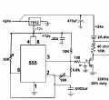
This circuit design worked for the 1st time I assembled it, but the second time I couldn't get the frequency less than 30Khz. It needs to be 22Khz with around 28% duty cycle. For the small duty cycle the design had to vary from the normal 555 astable design. How would you change it to lower the frequency and lower the duty cycle (it also was too high)?
 

Attachments

crutschow

Joined Mar 14, 2008
38,330
Increase the capacitor value to reduce the frequency.
Reduce the value of the variable 10kΩ resistor to reduce the duty-cycle.

(Note - It makes it a lot easier to discuss a circuit design if you label all the components).
 

Art Vandelay

Joined Nov 1, 2024
140
Give this circuit a whirl. I used the Electrodoc Android app to calculate the values. Replace the resistors with pots to dial in the exact duty cycle and frequency. Be sure to set the pots as close to the stated values with your multimeter before installing otherwise tuning will be a pain.

If you don't have these component values, R1=18k, R2=47k C=1nF will provide the same result.

thumbnail_Screenshot_20241117-101046.png
 

MisterBill2

Joined Jan 23, 2018
27,197
If the circuit is using the same components but on a plug-in breadboard, I would suspect a poor connection to one of the timing circuit components, probably a capacitor. OR a failed capacitor. Or misreading the colors on a resistor.
If the TS has a simulator, check the circuit with that and see what frequency and duty cycle result.
 
Top