555 Astable circuit to Stepper driver. Need to slow the frequency on startup

Thread Starter

Nealieboyee

Joined May 24, 2017
56
Apart from the added cap on the CV pin it's a standard circuit (if not the more frequently used 'textbook' circuit). You can replace R1 with a variable resistance (rheostat) to vary the frequency manually, in addition to the variation provided by the CV pin control. As usual with a rheostat, include a series fixed resistor to ensure the total resistance can't be set to zero Ohms.
Ah I see. So if I'm understanding this correctly, the CV pin is normally biased at 2/3VCC but the RC combo will start it at VCC and then drop back down to 2/3VCC after a second or so? Essentially giving the normal oscillator circuit back the control of the frequency?
 

Alec_t

Joined Sep 17, 2013
15,149
More or less. If there's an R from the CV pin to ground then the '2/3 Vcc' and the '1/3 Vcc' both get pulled down somewhat too.
 

Thread Starter

Nealieboyee

Joined May 24, 2017
56
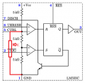
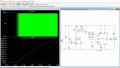
@crutschow and @Alec_t It works just as you said, Thanks. However, I have a question or two. Please forgive my ignorance, but wouldn't putting the 10K on pin 5 effectively do what I've highlighted in the below pics? It would cause the 100uF cap to discharge from VCC down to 1/2VCC. Alec is that what you meant by your last post when you said it would pull down the 2/3 and 1/3 VCC points?
I'm just trying to understand what this does to the frequency. The 10K resistor and the 22nF cap give it a frequency of around 3kHz, ignoring the ramp up. But besides providing the ramp up, do the 100uF and 10K resistor on pin 5 mess with the frequency at all?
I really appreciate your help.
 

Attachments

crutschow

Joined Mar 14, 2008
38,689
Yes, messing with the CTRL voltage affects both the frequency and the duty-cycle of the output.
Understand the the timing capacitor charges until it reaches the CTRL voltage, where the output then drops to zero.
Then when the capacitor voltage drops to the voltage at the bottom two resistors the output goes back high.

Obviously the time it takes for the capacitor to charge and discharge depends upon the value of those two voltages.
 

Thread Starter

Nealieboyee

Joined May 24, 2017
56
Thanks for that. So if you wanted to keep your frequency as close to what it was before messing with the control voltage (1/3 and 2/3 VCC) you could change the 10K on pin 5 to something much bigger that didn't impact the internal voltage divider circuit as much. But you'd be disharging your 100uF cap a lot slower so ramp up time would be increased?
 

Alec_t

Joined Sep 17, 2013
15,149
If the ramp-up time is increased then the frequency is decreased, unless you also decrease the cap discharge time to compensate.
 

Alec_t

Joined Sep 17, 2013
15,149
No. In my post #10 circuit, R1 affects both the charge and discharge times of C1. If you want to increase one at the expense of the other then you can use 'diode steering' by connecting a diode in series with a further resistor and connecting that series string in parallel with R1.
So if you wanted to keep your frequency as close to what it was before messing with the control voltage .....
Why? The aim of this thread, according to the title, is to vary the frequency.
 

Thread Starter

Nealieboyee

Joined May 24, 2017
56
Why? The aim of this thread, according to the title, is to vary the frequency.
Purely just me trying to understand how the circuit works. I've never seen this version of a 555 astable before, and I'm just trying to get my head around how R2 and C2 affect the frequency and duty cycle.
 

eetech00

Joined Jun 8, 2013
4,724
Hi
This hasn't been tested but might work for you.
I used an RC circuit to control a current mirror. The current mirror controls current thru the 555 timing circuit.
The circuit below ramps from 130 Hz to 2.4 Khz.

1662064739884.png
 

Thread Starter

Nealieboyee

Joined May 24, 2017
56
Hi
This hasn't been tested but might work for you.
I used an RC circuit to control a current mirror. The current mirror controls current thru the 555 timing circuit.
The circuit below ramps from 130 Hz to 2.4 Khz.

View attachment 275364
Thanks very much. I've got Alec's version working well but when I build another one I'll certainly try yours too.

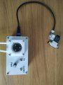
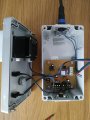
Just to update and give a decent end to this thread, here is the final build completed. I engraved a PCB for it too. It's a peristaltic pump and air solenoid for coolant/air control on my CNC mill. The control of the peristaltic with a stepper makes it so much easier to dial in the lubricant amount and is far better than those finnicky needle valves.
Thanks to @Alec_t and @crutschow for your help. I like to question exactly how things operate so when I build a circuit, I know exactly what is going on inside it. Thanks for your patience.
 

Attachments

Top