Facebook
 Google
 GitHub
 Linkedin
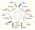
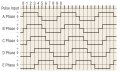
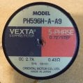
Hi all, I have a VEXTA PH596H-A-A9 type 5 phase (10 wire) stepper motor (0.72°/step, 2.7A, 0.43ohm, 1mH).
I would like to build the drive for it with these circuits, because I don't know how to program processors.
The ICs I have are L6203, (L6506), L297. The IC in brackets is also there, but maybe the motor direction
change would be easier to solve with L297. I would like to change the stepping speed of the motor with
a potentiometer controlled oscillator. The maximum speed of the motor is 2rpm.
The motor voltage can be 12V or 24V. Any help would be helpful to me in solving the motor control,
because so far I have found little information on the internet about the control of 5 phase stepper motors.
Can the above circuits alone be used to control a 5 phase motor?
Or should I try discrete circuits? Thank you.