5 Bit Random Number using multiple 555 Timers?

Thread Starter

amerfarooq

Joined Apr 28, 2017
9
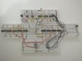
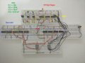
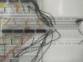
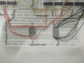
So, just want to know if this is possible. I'll use five 555 Timer IC's set at different frequencies so I'm thinking the clock pulses generated should be relatively random. Then I'll feed this into a 5 bit decoder that I'll have to make myself. But will this work? I'll use a switch to be able to stop the output of the 555 Timers so they all stop at the same time at some 5 bit number which I will then decode. The thing is, I cannot use Arduino or any micro-controller etc. I'm only allowed the 555 Timer IC and the basic logic gates.
 

dl324

Joined Mar 30, 2015
16,846
Welcome to AAC!

It'll be more random if you do something to make the timer frequencies change. Look at the timer control pin...
 

Thread Starter

amerfarooq

Joined Apr 28, 2017
9
Thank you! Actually this is a very small project. The randomness does need to be that..random. It seems like a silly thing to ask, but again, can this work?
 

AnalogKid

Joined Aug 1, 2013
10,987
Yes, it will work, although you don't explain what "decode" means. Another approach is to have a very fast 555 clock a 4- or 8-bit counter, and latch its output whenever you want a new number.

Do not connect the noise filter capacitor to pin 5. A little noise there increases randomness.

ak
 

Thread Starter

amerfarooq

Joined Apr 28, 2017
9
Our course is actually a beginners course so I'm not really that learned in all of this stuff. As for decode, I'm talking about building a 5 bit decoder that will decode the output from the timers so I can display the generated number on a double seven segment display. Again, I'm only allowed to use the 555 Timer IC and the basic logic gates. Nothing else. No counters or decoders or pretty much anything else.
 

ErnieM

Joined Apr 24, 2011
8,377
Sure it can work... but the requirements make this sound like a homework assignment.

The need to convert the 5 bit number to two BCD or binary coded decimal numbers to run the display is probably what prompted AnalogKid's comment of LOTSA gates. That is the tricky part. Making two BCD digits with 7 555's would be lots simpler.

Stopping the 555's may present a synchronization issue if they all restart with a similar pattern. Capturing any number on the fly with a latch would get past that as the (psudo) randomness is always preserved.
 

Bernard

Joined Aug 7, 2008
5,784
Should work. To stop the 555s we might clamp the timing cap. at 1/2 Vcc by using a 2 pole , single throw switch, and a pair of diodes for each of the 555s. As the diodes are reversed biased, they should not effect timing. Timing resistors should be in 100k range, 91k, 100k, 120k, 130k,150k. give or take.
Decoding might be done in 2 steps, 0-7 & 0-2, then a diode matrix for the 2 common anode displays.
Counter #1 00000.jpg Counter #2 00000.jpg
 

Thread Starter

amerfarooq

Joined Apr 28, 2017
9
Thank you for the replies everyone, especially @Bernard ! Unfortunately, due to time constraints, I've decided to just do a 3 bit number instead. But I've run into a problem. The thing is, I'm using the output of the 555 Timer's directly as my 3 bit number and I realized that in this way, I'll get 1's but not 0's. Is there a way to connect the 555 Timer's in such a way it gives me both HIGH and LOW? Or would I have to resort to a 3 bit counter and use its output. But in this way, I'll only need one Timer and I'll have to set its frequency very high and then pause it to land at some number which I can then decode. I'm a little confused on what to do. And I should've mentioned in the first post; my goal is to make a random number generator, in this case, of 3 bits. And I apologize If I'm making some heinous error! This is my first time doing such a project.
 

ErnieM

Joined Apr 24, 2011
8,377
I'd be hard pressed to come up with a 555 circuit that did not output ones and zeros so it is time for you to post your schematic and show your work.
 

AnalogKid

Joined Aug 1, 2013
10,987
In both astable and monostable modes of operation, a 555 output (pin 3, to be clear) must exist in both high and low states at some time(s) to operate. If yours is stuck in one state, there is a circuit error. No schematic = no answer.

Also, schematic = *your* schematic, not a cut and past from a website. Show the connections you made in assembling your physical circuit. Be sure to add a reference designator to each component to aid discussions.

ak
 

Bernard

Joined Aug 7, 2008
5,784
Your 3- 555s , free running, astable, oscillators should be close to 50% duty cycle & not using pin 7. You can add resistors & LEDs to the outputs & slow them down to several Hz so that you can monitor them. If Cx = .1 then use high value Rs, like 820k, 1M, 1.2M; or C = 1uF, Rs like before.
What do you have for gates & drivers; if necessary Rs, diodes, & transistors will work.
 

Thread Starter

amerfarooq

Joined Apr 28, 2017
9
Sorry for the late reply! I've attached the schematic and I've also included some pictures of the circuit if that helps. I also found out that I'm allowed to use an IC if I do part of the circuit myself. So, I've made a 3-bit counter and a 3-bit BCD to 7-seg decoder for the first 7-seg display. And for the second display, I've used a 4033 IC.

The idea is to have both the 555 Timer's at very high frequencies so nothing coherent shows up on both the displays. And then using a switch ( in the schematic I've used a DIP Switch, but in the circuit, I've used a single switch ) to stop the Timers at some number, which would be my random number. My range in this case would be from 00-79. But I'm facing an issue. I've tested the decoder intensively and it works perfectly. What I've noticed is that when my counter stops at some number, say 110, the number isn't decoded properly. Only when I directly ground the 0 part of the above number does the decoder display the correct number. The 1's work properly, but the 0's being output by the counter aren't actually 0's I think. I'm not sure if this makes sense.

In the pictures below, XYZ are the decoder inputs. X is yellow throughout the circuit, Y is off-white/grey and Z is green.
 

Attachments

ErnieM

Joined Apr 24, 2011
8,377
But I'm facing an issue. I've tested the decoder intensively and it works perfectly. What I've noticed is that when my counter stops at some number, say 110, the number isn't decoded properly. Only when I directly ground the 0 part of the above number does the decoder display the correct number. The 1's work properly, but the 0's being output by the counter aren't actually 0's I think. I'm not sure if this makes sense.
I have no idea what your "intensively" tested decoder is since it is described as both being "perfect" and not "decoded properly." Please make your comments using the reference designations off the schematic. "working properly" and "aren't actually 0's" are bad descriptions; voltages at referenced chip and pins number (ie, U12-10 is 1.2 VDC) is useful information.

I also note the schematic of your common cathode displays do not have any limiting resistors in series with each segment of the LEDs. You may have caused damage without these. There seems to be some sort of resistor in the build picture labelled-circuit-jpg but these are not noted in the schematic, and you need seven resistors, not one or two.
 

dl324

Joined Mar 30, 2015
16,846
I've tested the decoder intensively and it works perfectly.
In the simulator or on the breadboard?
What I've noticed is that when my counter stops at some number, say 110, the number isn't decoded properly.
What do you mean by 110? You have a two digit display.

Post your truth table and Kmaps.
Only when I directly ground the 0 part of the above number does the decoder display the correct number. The 1's work properly, but the 0's being output by the counter aren't actually 0's I think. I'm not sure if this makes sense.
Not making sense to me...

Is this homework?
 

Thread Starter

amerfarooq

Joined Apr 28, 2017
9
In the simulator or on the breadboard?
What do you mean by 110? You have a two digit display.

Post your truth table and Kmaps.
Not making sense to me...

Is this homework?
Oh sorry! I meant any number between 0-7. As for the decoder, yes I tested it on the breadboard and it works fine. I think the issue is that the decoded number isn't being properly displayed by the 7 segment display. And yes, this is a project.
 

dl324

Joined Mar 30, 2015
16,846
Oh sorry! I meant any number between 0-7. As for the decoder, yes I tested it on the breadboard and it works fine. I think the issue is that the decoded number isn't being properly displayed by the 7 segment display. And yes, this is a project.
So "110" means 6? And U1A is the LSB?

What is displayed for this case? Post your truth table and Kmaps for the decoder if you expect us try to help you; no one is going to take the time to reverse engineer your decoder...
 

Thread Starter

amerfarooq

Joined Apr 28, 2017
9
I have no idea what your "intensively" tested decoder is since it is described as both being "perfect" and not "decoded properly." Please make your comments using the reference designations off the schematic. "working properly" and "aren't actually 0's" are bad descriptions; voltages at referenced chip and pins number (ie, U12-10 is 1.2 VDC) is useful information.

I also note the schematic of your common cathode displays do not have any limiting resistors in series with each segment of the LEDs. You may have caused damage without these. There seems to be some sort of resistor in the build picture labelled-circuit-jpg but these are not noted in the schematic, and you need seven resistors, not one or two.
I didn't realize you had to use resistors with all the displays. Maybe thats why its giving a botched output. Which resistors should I use with it then? I've only used one for the e segment of the first display because it was giving me problems.

Sorry for being vague about all this! What I meant about the decoder was that I manually tested it for all numbers from 0-7 and it seems to give the correct outputs i.e. the correct number is displayed. But when I pass the outputs of the D flip flops (7474- pins 5 and 9) to the decoder, it doesn't show the correct number. And I cannot measure the voltages like you asked, I don't have any such equipment with me.
 

Thread Starter

amerfarooq

Joined Apr 28, 2017
9
So "110" means 6? And U1A is the LSB?

What is displayed for this case? Post your truth table and Kmaps for the decoder if you expect us try to help you; no one is going to take the time to reverse engineer your decoder...
No, the decoder works fine. Like I said before, when I manually pass it a number, it decodes it properly and it shows up fine on the display. But when I pass it a number from the counter, the correct number isn't displayed.

U2:A pin 5 is the MSB, U1:B pin 9 less significant, and U1:A pin 5 is the LSB.
 

dl324

Joined Mar 30, 2015
16,846
No, the decoder works fine. Like I said before, when I manually pass it a number, it decodes it properly and it shows up fine on the display. But when I pass it a number from the counter, the correct number isn't displayed.
This means the decoder isn't working.

Post the truth table and Kmaps for the decoder so we can verify your design.

When you pass the number from the counter and it isn't displayed correctly, what number are you passing and what is displayed?
 
Top