4066 help reqd

Thread Starter

kahafeez

Joined Dec 2, 2008
150
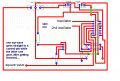
Hi all, i've been trying to make an FSK modulator..... the design is simple as shown in the figure..... bt the 4066 is not doing the switching very precisely.... plz suggest me something.... i think its not fast or i dont know what.... because if the square wave's freq is around 300bps which means 300 states in 1 sec... i dont knw whether this ic is that fast...


the problem is that i'm not even sure if this exactly is the problem.... see the results.... the oscilloscope at some time/div value tells that the signal is perfect.... while if we keep on going close then it shows the two freq mixed..
 

Attachments

Wendy

Joined Mar 24, 2008
23,415
To save others time the CD4066 is a quad CMOS switch. It's never a good idea to assume people know what you are using.

I'll study the schematic a bit.

**********

I believe some of your problem with the Oscope is trigger. Try triggering off the modulation signal only, not the FSK signal.

It looks like it should work. Not how I would have done it, but I don't know how precise your two signals need to be. I'd use a VCO, and a transistor myself.

I did not see a Vss. If you want to use a 4066 in analog mode you need this voltage to allow the output to swing both ways, plus and minus. Matter of fact, your drawing didn't show the Vcc either. You need the ± power supply to exceed the AC signals on the input for proper switching.

You also need to think very strongly about putting a buffer amp (transistor or op amp) after the 4066. I've done something similar for my stereo back when as an audio switch, and the output would intermittently cut off.
 
Last edited:

Thread Starter

kahafeez

Joined Dec 2, 2008
150
Sir thanks for replying, i did use a +5V supply with a -5V supply for the 4066..... and kept this in mind that the input signal shouldnt exceed the supply....

i think i'll change the design now and i'll work on the VCO thing.... i've created a new thread called PLL ic 4046 help......

plz help me there....
 

Thread Starter

kahafeez

Joined Dec 2, 2008
150
Audioguru can u plz explain what u just said a bit more.... wat i got is that u cant give 0V to the pin to go low without a resistor.... so i should add a resistor.... i'm actually giving a square wave to the switch for switching it on and off.... i'm using MC14066 and i'm using only two switches.... i've grounded the unused inputs and control pins and i've left the unused output pins open.... here the schematic of the 4066 i'm using....
 

Attachments

Audioguru

Joined Dec 20, 2007
11,248
You have pin 7 of the 4066 connected to -5V so the logic should be -5V for a low and +5V for a high. But the transistor gives +0.1V for a low so the 4066 does not turn off on the inverted channel.

The dual polarity supply is used when the input signals go positive and negative. If the signals go from 0V to +5V (or more) then the negative supply is not needed.
 

Thread Starter

kahafeez

Joined Dec 2, 2008
150
i'm actually giving a 0-5V square wave for turning the switches on and off..... while the thing wat i want to pass when the switch is on is a 3Vpp sine wave.... one of 212KHz and one of 243KHz...... plz suggest me the solution..... i think u r right the switch doesnt completely turn of when the square wave is low that is y the two signals are mixing.... plz tell me the solution....


i think i cant give gnd to pin7 bcz the sine wave has + and - both sides.....
 
Top